Indexed In
- Open J Gate
- Genamics JournalSeek
- Ulrich's Periodicals Directory
- RefSeek
- Directory of Research Journal Indexing (DRJI)
- Hamdard University
- EBSCO A-Z
- OCLC- WorldCat
- Proquest Summons
- Scholarsteer
- Publons
- Geneva Foundation for Medical Education and Research
- Euro Pub
- Google Scholar
Useful Links
Share This Page
Journal Flyer
Open Access Journals
- Agri and Aquaculture
- Biochemistry
- Bioinformatics & Systems Biology
- Business & Management
- Chemistry
- Clinical Sciences
- Engineering
- Food & Nutrition
- General Science
- Genetics & Molecular Biology
- Immunology & Microbiology
- Medical Sciences
- Neuroscience & Psychology
- Nursing & Health Care
- Pharmaceutical Sciences
Research Article - (2019) Volume 9, Issue 3
Treatment of Shale Oil Produced Water with Zwitterion-modified Forward Osmosis Membrane
Kommalapati R.R.1,2*, Hongbo Du1, Potluri S.P.1 and Botlaguduru V.S.V.12Department of Civil and Environmental Engineering, Prairie View A&M University, Prairie View, Texas, USA
Received: 15-Jul-2019 Published: 12-Aug-2019
Abstract
Shale oil extraction with hydraulic fracturing consumes large volumes of 3 freshwaters and produces Produced Water (PW) with a high level of organic and 4 inorganic contaminants. This study applied a Forward Osmosis (FO) process to treat shale oil Produced Water (PW) obtained from a Permian Basin shale play in Texas. The FO membrane surface was modified with 3-(3,4-dihydroxyphenyl)-L-alanine (L-DOPA) coating to enhance membrane fouling resistance. The membranes were characterized before and after coating, with contact angle measurement and Attenuated Total Reflection Fourier Transform Infrared (ATR-FTIR) spectroscopy. The L-DOPA coated FO membrane was utilized to treat PW in a Pressure Retarded Osmosis (PRO) mode, after preliminary filtration with 0.1, 0.2 or 0.45 μm filters. Optimum performance of water flux and flux recovery was observed when pre-treated with 0.1 μm. The coated membrane was further used to filter simulated PW, and diluted PW which was similar to Eagle Ford PW with TDS around 29,000 mg/L. Results showed that the zwitterionic coating reduced organic matter deposition on the membrane surface, and repelled salt ions to alleviate internal concentration polarization.
Keywords
Shale oil produced water; Forward osmosis; Zwitterionic modification
Abbrevations
FW: Flowback Water; PW: Produced Water; MF: Microfiltration; UF: Ultrafiltration; TDS: Total Dissolved Solids; FO: Forward Osmosis; NF: Nanofilration; RO: Reverse Osmosis; CTA: Cellulose Triacetate; AAS: Alginic Acid Sodium; DI: Deionized; COD: Chemical Oxygen Demand; TOC: Total Organic Carbon; PRO: Pressure-Retarded Osmosis; ATR-FTIR: Attenuated Total Reflection-Fourier Transform Infrared
Introduction
The future of fossil fuel supply in the U.S. is dominated by the unconventional hydrocarbon extraction from shale fracking operations. However, the exploration and production of shale gas and oil consume substantial amounts of freshwater, with much of it returning from wells in the form of Flowback Water (FW) and Produced Water (PW) [1-4]. PW contains high levels of organic and inorganic compounds. A single well can generate up to 5 million liters of PW during its lifetime [5]. PW and FW need to be treated to meet the federal and state regulations before discharge to surface water and groundwater in the U.S. FW may be easily reused in hydrofracking of new neighboring wells. However, reuse of PW is limited by the availability of new wells being developed in surrounding areas. Discharge of large volumes of PW has become a major ecological problem [6,7] and a serious public concern. The industry is currently struggling to dispose of PW through, for example, underground injection, which has generated a host of additional concerns.
Various membrane technologies are widely applied in bioseparation [8,9] and treatment of industrial and municipal wastewater after necessary pre-treatment [10,11]. Microfiltration (MF) and Ultrafiltration (UF) have been used to pre-treat conventional oil PW for a long time, and NF and RO are widely used to treat brackish water [7,12-16] that contains low Total Dissolved Solids (TDS). However, it is extremely difficult to establish high hydraulic pressure to overcome the osmotic pressure caused by high salinity of PW with high TDS; for that reason, NF and RO do not work well for treatment of the PW with high TDS. Membrane distillation [15,17-23] has also been widely explored to treat PW, but it suffers from huge energy consumption, contamination of the permeate caused by volatile organic compounds and dissolved gases in PW, and membrane failure caused by alcohols and surfactants in PW [6,24-27]. Among various membrane technologies, Forward Osmosis (FO) is very promising because of its natural working principle and light membrane fouling [28-30]. In contrast to pressure-driven membrane processes, such as MF, UF, Nanofilration (NF), and Reverse Osmosis (RO), FO is naturally driven by the osmotic pressure gradient.
FO process has been explored for industrial wastewater treatment, seawater desalination, electricity generation, food processing, and shale gas and oil PW treatment [12,29-35]. Cellulose Triacetate (CTA) and thin film composite FO membranes were tested in shale gas and oil PW treatment, and their performances and membrane fouling were evaluated [12,34-36]. There is less membrane fouling in FO than RO or NF due to the absence of hydraulic pressure. However, the intense energy costs of draw solute regeneration and membrane fouling have impeded the use of FO filtration for wastewater treatment [33]. Comprehensive studies showed that zwitterionic polymers coated on the membrane surface could dramatically reduce biofilm formation, resist short-term bacterial adhesion, and enhance membrane self-cleaning [37,38]. Recently, various zwitterionic polymers have been explored as surface modifiers of some substrates and osmotically driven membranes for wastewater treatment, such as high salinity shale gas PW and grey water, and osmotic power generation [39-43], and these modifications have improved the membrane antifouling properties.
Poly amino acid 3-(3,4-dihydroxyphenyl)-L-alanine (L-DOPA) is a zwitterionic polymer, which has been used to modify membrane surface for enhancing membrane antifouling properties [44-47]. Nguren et al. recently modified CTA FO membranes (Hydration Technology Innovations LLC, USA) with poly L-DOPA. Their study demonstrated that a better antifouling improvement for the FO membrane was achieved with 12-h modification when filtering a solution containing 1g/L Alginic Acid Sodium (AAS) and 0.2 g/L CaCl2 salts [48]. Their success inspired us to challenge a zwitterion-modified FO membrane in PW treatment with high concentration salt present in PW. To the best of our knowledge, there is no report of a zwitterion-modified FO membrane used in shale gas and oil PW treatment. In our work, the flux behavior of a CTA FO membrane modified with the same poly L-DOPA as before was investigated in the treatment of shale oil PW. The effects of some pre-treatments on PW were also evaluated, and these pre-treatments were vacuum microfiltration with 0.1, 0.2, or 0.45 μm filters.
Materials and Methods
3-(3,4-dihydroxyphenyl)-L-alanine (L-DOPA) (≥ 98%) and Tris (hydroxymethyl) aminomethane (Tris) (≥ 99.8%) were obtained from Sigma-Aldrich (USA). Different salts AAS, NaCl, KCl, Na2SO4, MgCl2 and CaCl2 with the purity at the ACS reagent level were purchased from Fisher Scientific, Inc. (USA). Deionized water (DI) (1 megaohm/cm) was first used in FO process to examine the membrane flux performance. Feed solutions are a typical organic foulant solution, Permian Basin PW, diluted PW and simulated PW. The organic foulant solution contains 1 g/L AAS and 0.2 g/L CaCl2. The raw Permian Basin PW was obtained from a shale oil company which is extracting shale oil in Permian Basin. The diluted PW was obtained by reducing the TDS of the Permian Basin PW with DI water to 29,000 ppm with deionized (DI) water dilution, which is similar to the TDS of the Eagle Ford PW [48]. The simulated PW was made from various salts according to the major salt ion concentrations of Permian Basin PW. It contained major salt ions such as Na+, Ca2+, Mg2+, K+, Cl- and SO42- present in the Permian Basin PW, and these ion concentrations are the same as the corresponding ion concentrations of the real Permian Basin PW. 2 M NaCl solution was first used as the draw solution when the feed solution is the organic foulant solution. 2 M MgCl2 solution was used as the draw solution for the FO treatment of PW because MgCl2 can generate 65.8% more osmotic pressure compared to the same concentration of NaCl. 110 μm CTA FO membranes were purchased from Fluid Technology Solutions, Inc. (Albany, OR).
Characterization of water samples
Different solids present in the water samples were determined according to the 2005 Standard Methods 2540B-2540F. These solids are classified as total solids, total volatile solids, total fixed solids, total suspended solids, volatile suspended solids, fixed suspended solids, total dissolved solids (TDS), volatile dissolved solids, and fixed dissolved solids. Chemical Oxygen Demand (COD) was measured by using a reactor digestion method (Hach’s Method 8000 approved by United States environmental protection agency, i.e., Standard Method 5220 D). Analysis of different salt ions, silicon organic nitrogen, and total organic carbon (TOC), was conducted by a commercial Lab SGS Accutest (Dayton, NJ). The particle size distribution of PW after the pre-treatment with 0.45, 0.2, or 0.1 μm filter was determined by using a nanosizer (Nano ZS Zetasizer, Malvern Instruments Inc, UK). The osmotic pressures of the PW and draw solution were measured by an osmotic pressure meter (5002 Osmette A, Precision Systems Inc., USA).
Surface modification of FO membrane
A 10 mM Tris-HCl buffer solution was used to dissolve L-DOPA. The L-DOPA concentration was 2 g/L, and the pH of the buffer solution was adjusted to 8.0. The solution was well mixed with a magnetic stirrer, and it was used to coat FO membranes on the porous side with a typical bench-scale FO system shown in Figure 1.
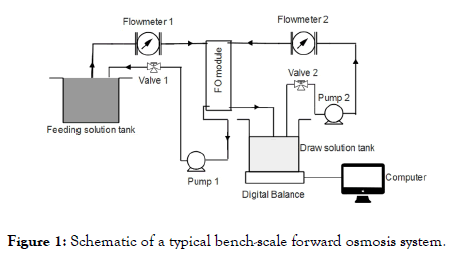
Figure 1. Schematic of a typical bench-scale forward osmosis system.
The FO system consists of a membrane cell, two circulating gear pumps, two tanks of feed and draws solutions, a digital balance (linearity 0.006 g), and a computer. When an FO membrane is loaded at the center of the membrane cell, two symmetric flow channels form on both sides of the membrane with an effective membrane surface area of 42.09 cm2.
During the surface modification of an FO membrane, the FO membrane was loaded in the membrane cell in a Pressure- Retarded Osmosis (PRO) mode, which implies that the active layer of FO membranes is facing the draw solution. The buffer solution containing L-DOPA was applied on the feeding side, and the other draw side was circulated with DI water. Depending on the pre-determined coating time, the L-DOPA solution was circulated to coat the membrane at 25.0 cm/s. The coating time varied from 8 to 14 h. After coating for a specialized and preselected time period, the membranes were washed with DI water 3 times and preserved in the refrigerator at 4°C
Membrane characterization
The water contact angle of the membrane surface, which indicates the hydrophilicity of the membrane, was measured by using a CAM-PLUS contact angle meter. Attenuated total reflection-Fourier transform infrared (ATR-FTIR) spectra of the virgin and modified membranes were obtained in the range of 4000-800 cm-1 (Shimadzu IRAffinity-1 spectrometer with MIR acle 10 single reflection ATR accessory).
FO process
All the FO experiments were conducted in the PRO mode because it is easy to modify the support layer side of a commercial FO membrane and the PRO mode achieves higher water flux than the FO mode. The typical organic foulant solution was used to standardize the coating time of poly L-DOPA on the porous side of the FO membrane. Shale oil PW that went through vacuum filtration with 0.1, 0.2 or 0.45 μm filter was fed on the feed side. The cross-flow rates of the feed and draw solutions were maintained at 25.0 cm/s and the flux behavior of the virgin and coated membranes during PW treatment were observed for 12 h. The weight change of the draw solution tank (i.e. the weight change of permeate) was measured with the digital balance at every minute and was recorded by the computer. The weight change of permeate was used to calculate the water flux (Jw) during each min with the following equation:

Results and Discussion
Standardization of L-DOPA coating on the FO membrane surface
The coating time of poly L-DOPA on the FO membrane surface was standardized by feeding the typical organic foulant solution containing AAS and CalCl2, and using 2 M NaCl solutions as draw solution. Before coating, the flux insistency of the virgin FO membranes were checked by feeding DI water and using 2 M NaCl solution as draw solution. Although Nguyen et al. optimized the L-DOPA modification time of a CTA FO membrane surface as 12h [49], we still need to justify it because our CTA FO membranes were obtained from a different company. The flux behaviors of the uncoated and coated FO membranes were analyzed along operating time. The flux changes were observed by plotting normalized fluxes (J/Jo) (Figure 2), where J is the real-time flux, and Jo is the initial flux. In order to clearly show the flux trends, a moving average function that averages 10 data points was applied.
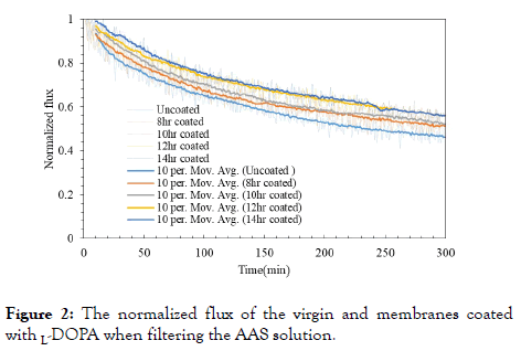
Figure 2. The normalized flux of the virgin and membranes coated with L-DOPA when filtering the AAS solution.
After 300 min of FO treatment, the virgin membrane exhibited flux reduction to 46.2% while the membranes with L-DOPA coating showed less flux decline. It can be seen that the normalized flux decreased to 51.9% for the 10h coated membranes, 55.4% for the 12h and 56% for the 14h. The flux of the 8h coated membrane reduced similarly to the 10h coated membrane. The flux behavior of the 12h and 14h coated membrane is also similar, so the coating time was standardized to 12h as same as the previous report [49].
Surface characterization of FO membranes
The improvement in hydrophilicity of the coated membrane surfaces was examined using contact angle analysis. It showed that the membrane wettability was directly related to the coating time. Initially, the contact angle was 46.0° for the uncoated membrane, and it reduced to 40.4° for the 8h coating, to 39.2° for the 10h, and to 36.8° for the 12h. The decline of contact angle with an increase in coating time is attributed to more distributed poly L-DOPA on the surface of the membrane support layer. Poly L-DOPA is a zwitterionic polymer possessing a cationic and an anionic unit, and more favorable to attract water molecules than the original material of the support layer. The distribution intensity of poly L-DOPA on the support layer increases with the increased coating time, and thus the hydrophilicity of the membrane surface increases.
The ATR-FTIR spectra of the virgin and L-DOPA modified FO membranes are shown in Figure 3. It is well known that poly L-DOPA and the CTA FO membrane have three functional groups in common such as -C-O-C-, -C=O, and -O-H, which can be detected from ATR-FTIR spectroscopy. The peak at approximate 3500 cm-1 represents the existence of the -O-H group, the peak appearing at 1750 cm-1 is identified as the -C=O group and the peaks appearing at 1050 and 1250 cm-1 are caused by the -C-O-C- group. These peaks were previously identified by Ilharco et al. [50] as the presences of -C=O, -O-H and -C-O-C- groups in CTA films during the aggregation of cyanine on the films. It is seen that the transmittance intensities of the bands of the groups C=O and -C-O-C- decease with the coating time because more CTA is covered by poly L-DOPA with the increase of the coating time. The numbers of the groups - C=O and -C-O-C- in poly L-DOPA per unit area are smaller than those in the CTA material. The peaks of the -O-H group present in the CTA membrane disappeared in the 8-,10, and 12h coated membranes, and this was attributed to the chemical reactions between the catechol group of L-DOPA and the -O-H group on the CTA membrane surface.
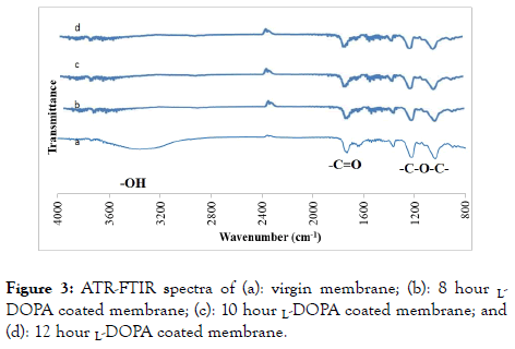
Figure 3. ATR-FTIR spectra of (a): virgin membrane; (b): 8 hour LDOPA coated membrane; (c): 10 hour L-DOPA coated membrane; and (d): 12 hour L-DOPA coated membrane.
Produced water characterization
Table 1 lists pH, nine solids of the raw Permian Basin PW and concentrations of some particles and various salt ions present in PW after the 0.45 μm filtration. When COD of the raw PW was measured, the raw PW was diluted 25 times. The pH of 7.48 indicates that PW is slightly basic and it is ready for vacuum MF followed by FO treatment. The raw PW has a high TDS of 124,920 mg/L and TOC of 168 mg/L, which agree with the previous findings investigated by Khan et al. [46]. However, the raw PW contains low total suspended solids of 140 mg/L compared to the previous report. The concentrations of sodium and chloride ions are 32,300 mg/L and 48,100 mg/L, and they are the major ions in PW. The osmotic pressure of PW, diluted PW, and 2 M MgCl2 draw solution are 63.1, 8.50 and 203 atm, respectively. The measured TDS and osmotic pressure had no obvious change after performing the different micro filtrations.
| Analyte | Water sample | Unit | pH or concentration |
|---|---|---|---|
| pH | Raw produced water (PW) | - | 7.48 |
| Total solids | Raw PW | mg/L | 125,060 |
| Total volatile solids | Raw PW | mg/L | 65,060 |
| Total fixed solids | Raw PW | mg/L | 60,000 |
| Total suspended solids | Raw PW | mg/L | 140 |
| Volatile suspended solids | Raw PW | mg/L | 80 |
| Fixed suspended solids | Raw PW | mg/L | 60 |
| Total dissolved solids (TDS) | Raw PW | mg/L | 124,920 |
| Volatile dissolved solids | Raw PW | mg/L | 64,980 |
| Fixed dissolved solids | Raw PW | mg/L | 59,940 |
| Chemical oxygen demand | Raw PW | mg/L | 2,125 |
| Barium | PW After 0.45 µm filtration | mg/L | 3.7 |
| Boron | PW After 0.45 µm filtration | mg/L | 51.0 |
| Calcium | PW After 0.45 µm filtration | mg/L | 2,200 |
| Iron | PW After 0.45 µm filtration | mg/L | 0.5 |
| Lithium | PW After 0.45 µm filtration | mg/L | 22.1 |
| Magnesium | PW After 0.45 µm filtration | mg/L | 448 |
| Manganese | PW After 0.45 µm filtration | mg/L | 1.1 |
| Potassium | PW After 0.45 µm filtration | mg/L | 563 |
| Silicon | PW After 0.45 µm filtration | mg/L | 11.4 |
| Sodium | PW After 0.45 µm filtration | mg/L | 32,300 |
| Sulfur | PW After 0.45 µm filtration | mg/L | 63.1 |
| Bromide | PW After 0.45 µm filtration | mg/L | 416 |
| Chloride | PW After 0.45 µm filtration | mg/L | 48,100 |
| Fluoride | PW After 0.45 µm filtration | mg/L | 7.6 |
| Nitrogen, Ammonia | PW After 0.45 µm filtration | mg/L | 409 |
| Nitrogen, Nitrite | PW After 0.45 µm filtration | mg/L | 3.4 |
| Nitrogen, Total Kjeldahl | PW After 0.45 µm filtration | mg/L | 756 |
| Nitrogen, Total Organic | PW After 0.45 µm filtration | mg/L | 347 |
| Sulfate | PW After 0.45 µm filtration | mg/L | 144 |
| Total Organic Carbon (TOC) | PW After 0.45 µm filtration | mg/L | 168 |
Table 1: Analysis of Permian Basin produced water.
The size distributions of particles are presented in Figure 4 after the raw PW is filtered through vacuum filtration using 0.1, 0.2 or 0.45 μm filter. The major particles after 0.2 or 0.45μm filtration are dominated in the size range of 2-7.4 μm.
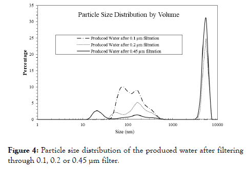
Figure 4. Particle size distribution of the produced water after filtering through 0.1, 0.2 or 0.45 µm filter.
Compared to the 0.45 μm filtration; fewer particles after the 0.2 μm filtration are present in this range. After 0.1 μm filtration, the particle sizes distribute in a broad range of 40-550 nm. The PW filtration with 0.1 μm would benefit for the later FO process, however, it requires more energy than the other two.
Effects of microfiltration on the treatment of PW with FO membranes
In order to investigate the effects of MF on the performance of the later FO membrane process, three batches of the raw PW were individually filtered through 0.1, 0.2 or 0.45 μm filter, and were fed to the FO system. In all the FO experiments, the initial volumes of the fed PW and the draw solution are 2 L, and 1 L of 2 M MgCl2 solution, respectively. The virgin CTA membrane was tested first. The actual water fluxes at the beginning and end of the FO process are listed in Table 2.
| Membrane | 0.1 µm filter | 0.2 µm filter | 0.45 µm filter | |||
|---|---|---|---|---|---|---|
| Beginning | End | Beginning | End | Beginning | End | |
| Virgin FO membrane | 7.4 | 3.7 | 7.0 | 3.5 | 6.8 | 3.4 |
| L-DOPA modified FO membrane | 6.7 | 3.6 | 6.3 | 3.2 | 6.0 | 3.0 |
Table 2: Actual water flux of FO filtration after Permian Basin PW was pretreated with different micro filters (Unit: L/(m2·h)).
Figure 5 represents the normalized flux behavior of the virgin membrane after the raw PW was pre-filtered with 0.1, 0.2 or 0.45 μm filter. In the initial stage of the experiments, a sudden drop in flux around 10% was observed, and this could be attributed to the quick fouling during the FO process with the virgin membrane. The flux decline appeared to be linear throughout the rest of the experiment.
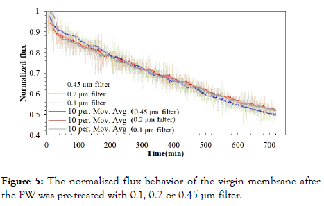
Figure 5. The normalized flux behavior of the virgin membrane after the PW was pre-treated with 0.1, 0.2 or 0.45 µm filter.
The flux declined to about 50% of the initial value, after 12h in all three cases. Although no significant difference can be detected among the three flux curves, the marginal difference can be observed after 500 min. The pre-treatment conducted with 0.1 and 0.2 μm filters, show slightly higher fluxes, than that the 0.45 μm filtration. Overall, it can be inferred decreasing the pore size of microfiltration filters, only results in marginal improvement for FO process.
Figure 6 describes the normalized flux behavior of the L-DOPA coated membrane after the raw PW was pre-treated with 0.1, 0.2 or 0.45 μm filter. There did not exist an initial stage in these three fluxes like the initial behavior observed for the uncoated FO process. Among the three cases, the L-DOPA coated membrane exhibited the best performance after the raw PW was pre-filtered with 0.1 μm filter. Even in the other two cases of the prefiltration with 0.1 and 0.2 μm filters, some clear differences in the FO fluxes can be seen till 500 min. After 500 min of FO process, the normalized fluxes of the two FO processes are similar. After 720 min, the 0.1μm case has 3.5% higher flux than the 0.45 μm case. It is obvious that the 0.1 μm filter inhibits more particles than the other two during the pretreatment, and would benefit for the later FO process. It is interesting that different flux behaviors were observed for the virgin and coated FO membranes after the raw PW was prefiltered with 0.1, 0.2 or 0.45 μm filters. The flux differences were very small for the virgin membrane after three individual MFs, and the flux differences were clearly present for the zwitterion-modified membrane. It demonstrates that the L-DOPA modification of the FO membrane surface works well for PW treatment and the better performance is achieved when more particles are removed in the MF pre-treatment. The L-DOPA coating on the support layer of CAT FO membrane repels organic compounds and salt ions from the FO membrane surface to some degree, thus improving the membrane antifouling properties. When the sizes of particles present in PW gets smaller, the L-DOPA coating exhibits better performance.
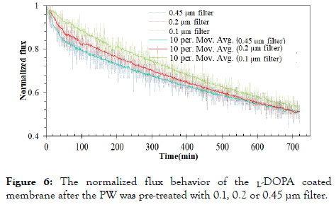
Figure 6. The normalized flux behavior of the L-DOPA coated membrane after the PW was pre-treated with 0.1, 0.2 or 0.45 µm filter.
An improvement of the flux recovery is also achieved by zwitterionic modification of the FO membrane surface. The recovery of the membrane indicates the amount of flux that can be gained after cleaning the membrane. After running for 12h, the FO membranes were cleaned by hydraulic flushing, which was verified to completely recover the water flux to its initial status in the treatment of real coal seam gas associated water [51]. The flux recovery rates of the uncoated and coated FO membranes used in our PW treatment are listed in Table 3.
| Membrane | 0.45 µm filter | 0.2 µm filter | 0.1 µm filter |
|---|---|---|---|
| Virgin FO membrane | 65.5% | 73.1% | 75.0% |
| L-DOPA modified FO membrane | 67.9% | 76.9% | 78.0% |
Table 3: FO membrane recovery when the PW is pretreated with microfiltration.
The uncoated membrane has less flux recovery than the L-DOPA coated membrane, and the flux recovery in the 0.1 μm case is higher than the other two cases for both membranes. The L-DOPA coated membrane shows a recovery of 2.4%-3.8% higher than that of the uncoated membrane. The highest recovery of 78.0% was achieved for PW filtration with L-DOPA coated membrane after the raw PW was pre-filtered with 0.1 μm filter.
Our recovery rates are 22%-35% lower than the flux recovery in the previous study [51], and the reason is that the Permian Basin PW is a more complex mixture than the real coal seam gas associated water used in the earlier study. Both observations of membrane flux and flux recovery here suggest that PW can be better treated with the L-DOPA coated membrane after it is prefiltered with 0.1 μm filter.
Antifouling mechanism of L-DOPA coating with diluted PW and simulated PW
In order to further observe the flux behavior of the L-DOPA coated FO membrane in the treatment of different PW and investigate the influence of organic compounds and salt ions on the membrane performance, diluted PW and simulated PW were also applied to the FO process. The FO experiments of the diluted PW were conducted after the diluted PW was prefiltered with 0.1 μm filter. The concentrations of all the species in the PW are reduced in the dilution, so higher flux and less fouling are expected in the FO treatment of the diluted PW. The simulated PW was used to investigate the influence of salt ions without the organics on the flux behavior of the L-DOPA coated FO membrane.
Effect of L-DOPA coating on the treatment of diluted PW: The FO treatment of diluted PW was conducted with the virgin and coated membrane for 12 h. Both actual water fluxes of FO process of diluted PW after pre-treated with 0.1 μm filters are listed in Table 4, and the normalized fluxes are presented in Figure 7.
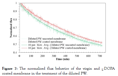
Figure 7. The normalized flux behavior of the virgin and L-DOPA coated membrane in the treatment of the diluted PW.
| Membrane | Diluted PW | Simulated | ||
|---|---|---|---|---|
| Beginning | End | Beginning | End | |
| Virgin FO membrane | 15.8 | 7.6 | 7.0 | 4.0 |
| L-DOPA modified FO membrane | 14.4 | 7.5 | 6.8 | 4.0 |
Table 4: Actual water flux of FO filtration of diluted PW after pretreated with 0.1 µm filters and simulated PW (Unit: L/(m2·h)).
It is evident that zwitterionic modification of the FO membrane surface has a significantly positive effect on the performance of diluted PW treatment compared to the treatment of the Permian Basin PW. After 12h process, the L-DOPA coated membrane has flux reduced to 52.0% while the uncoated membrane exhibited reduction to 48.4%. The L-DOPA coated membrane has more advantage to treat the diluted PW due to its lower organic content and TDS present. The L-DOPA coating on the support layer in our study is comparable to the surface modification of an osmotically driven membrane, which was coated with 2-methacryloyloxyethyl phosphorylcholine (MPC) on its membrane support layer, and was used in power generation from municipal wastewater [52]. In our FO process of diluted PW, the water flux recovery rates of the virgin and 12 h L-DOPA coated membranes are 91.5% and 93.5%, respectively. Both recovery rates are much higher than the corresponding recovery rates in the treatment of the Permian Basin PW due to lower fouling rate with the diluted PW.
Comparison of the treatments of Permian Basin PW, diluted PW and simulated PW: Simulated PW can be considered as ideal PW in which organic compounds are removed during the primary and secondary treatments. When the simulated PW is fed to FO, membrane fouling is not a significant factor, due to the salt concentrations in being much lower than salt solubility in water. The interactions of zwitterionic polymers with salt ions were recently modeled by Leng et al. [53], and their findings showed that the densely grafted zwitterionic polymers on a substrate have the ability to repel salt ions from the substrate. Our experiments with simulated PW treatment using the virgin and L-PODA coated FO membrane demonstrated that the L-PODA coated FO membrane had greater flux because the salt ions were repelled from the membrane surface by poly L-PODA and the Internal Concentration Polarization (ICP) in the support layer of the FO membrane was alleviated. Figure 8 presents the comparison of normalized water flux behavior of the L-PODA coated FO membrane during the treatment of Permian Basin PW, diluted PW and simulated PW. In contrast to Figures 2 and 5-7, only the 10 min moving average plots are presented in Figure 8, to separate noise and fluctuations due to the experimental setup. This comparison of moving averages allows for better identification of macro trends, by minimizing background noise. During the first 200 min, the flux behaviors of three cases are similar, and the flux behavior in the diluted PW treatment is slightly better than the case of Permian Basin PW. From 200 min, the flux behavior in the case of simulated PW deviated from the other two, and some flux fluctuations appeared after 300 min. After running for 12h, the flux of simulated PW reduced to 58.1% which is much greater than those for the two cases of Permian Basin PW and diluted PW.
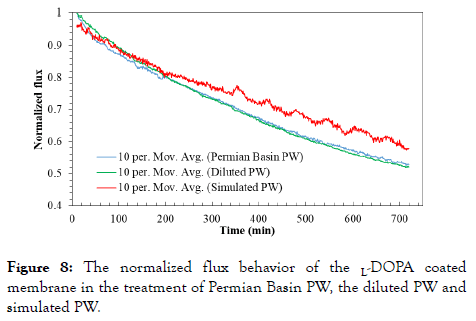
Figure 8. The normalized flux behavior of the L-DOPA coated membrane in the treatment of Permian Basin PW, the diluted PW and simulated PW.
Strong hydration of zwitterionic terminals is believed to be the key antifouling mechanism of such zwitterionic coatings [54]. After the FO membrane surface was modified with zwitterionic L-DOPA polymers, a negatively charged ultrathin film was developed on the membrane surface, enhancing the hydrophilicity of the membrane surface.
Thus, the resistance to organic fouling was improved. During the FO process of PW, salt cations and anions present in PW interacts with the partial positive and negative charges of zwitterionic polymers distributed on the membrane surface, and a metastable thin water layer develops on the membrane surface [55]. The thin layer further helps to prevent organic fouling because the metastability slows down the diffusion of organic compounds, salt ions and water molecules in it. Observed from the flux comparison of three cases, the flux behavior in the case of simulated PW is much better than the other two. There is no doubt that in the case of simulated PW the membrane can be 100% recovered with hydraulic cleaning even some salt deposits on the membrane surface. During the FO treatment of Permian Basin PW and diluted PW, various particles, especially organic foulants, accumulated on the membrane surface more and more during the 12h period, and their flux recovery was 78.0% and 93.5%, respectively. This suggests that it would be much better to remove organic compounds before the FO treatment, thus avoiding organic fouling on the membrane surface and reducing the operating cost of membrane cleaning during FO treatment [56]. It could be done through digestion of PW organic compounds with the aid of efficient photocatalysts, ozone, and H2O2 in the PW pre-treatment.
Conclusions
In this study, a controlled circulating method was employed to directly deposit L-DOPA on the support layer of a commercial FO membrane, and a coating time of 12h was found to be optimized. The L-DOPA coated FO membranes were used to treat shale oil PW obtained from Permian Basin shale play, after pre-filtration with 0.45, 0.2 or 0.1 μm filters. In the PW treatment with FO membranes, the coated FO membrane demonstrated enhanced fouling resistance than the virgin membrane, and the best performance of the coated FO membrane was achieved after the raw PW was pre-filtered with 0.1 μm filter. Membrane flux recovery by backwashing also improved with zwitterionic coating, compared to the virgin membrane. The coated FO membrane was further used to filter diluted PW in which TDS is similar to that of Eagle Ford PW, and simulated PW which has the same ion concentrations of major salt ions present in Permian Basin PW. Results from this study indicate that zwitterionic modification of FO membrane surface not only hinders organic fouling on the FO membrane but also repels the salt ions to alleviate ICP when PW, which has high TDS, is filtered with zwitterion-modified FO membrane. Results from this study indicate that surface modification of FO membranes would be a potential process alternative for PW treatment, and further studies with multiple coatings could elucidate details on the fouling mechanism. This study could serve as a benchmark for establishing the value of integrating FO process as a component of sequential membrane systems for PW treatment.
REFERENCES
- Zhang D, Tingyun YA. Environmental impacts of hydraulic fracturing in shale gas development in the United States. Petroleum Exploration and Development. 2015;42(6):876-883.
- Pacsi AP, Sanders KT, Webber ME, Allen DT. Spatial and temporal impacts on water consumption in Texas from shale gas development and use. ACS Sustain Chem Eng. 2014;2(8):2028-2035.
- Chang Y, Huang R, Masanet E. The energy, water, and air pollution implications of tapping China's shale gas reserves. Resour Conserv Recy. 2014;91:100-108.
- Clark CE, Horner RM, Harto CB. Life cycle water consumption for shale gas and conventional natural gas. Environ Sci Technol. 2013;47(20):11829-11836.
- Cozzarelli I, Akob D, Mumford AC. Impact of unconventional shale gas waste water disposal on surficial streams. In AGU Fall Meeting Abstracts 2014.
- Shaffer DL, Arias Chavez LH, Ben-Sasson M, Romero-Vargas Castrillo´n S, Yip NY, Elimelech M. Desalination and reuse of high-salinity shale gas produced water: drivers, technologies, and future directions. Environ Sci Technol. 2013;47(17):9569-9583.
- Estrada JM, Bhamidimarri R. A review of the issues and treatment options for wastewater from shale gas extraction by hydraulic fracturing. Fuel. 2016;82:292-303.
- Liu Z, Du H, Wickramasinghe SR, Qian X. Membrane surface engineering for protein separations: experiments and simulations. Langmuir. 2014;30(35):10651-10660.
- Himstedt HH, Du H, Marshall KM, Wickramasinghe SR, Qian X. pH responsive nanofiltration membranes for sugar separations. Ind Eng Chem Res. 2013; 52(26):9259-9269.
- Kang GD, Cao YM. Development of antifouling reverse osmosis membranes for water treatment: a review. Water Research. 2012;46(3):584-600.
- Al Abdulgader H, Kochkodan V, Hilal N. Hybrid ion exchange-Pressure driven membrane processes in water treatment: A review. Sep Purif Technol. 2013;116:253-264.
- Coday BD, Cath TY. Forward osmosis: Novel desalination of produced water and fracturing flowback. J Am Water Works Ass. 2014;106(2):E55-66.
- Fakhru’l Razi A, Pendashteh A, Abdullah LC, Biak DR, Madaeni SS, Abidin ZZ. Review of technologies for oil and gas produced water treatment. J Hazard Mater. 2009;170(2-3):530-551.
- Mondal S. Polymeric membranes for produced water treatment: an overview of fouling behaviour and its control. Reviews in Chemical Engineering. 2016;32(6):611-628.
- Munirasu S, Haija MA, Banat F. Use of membrane technology for oil field and refinery produced water treatmen-A review. Process Safety and Environmental Protection. 2016;100:183-202.
- Cvorovic J, Passamonti S. Membrane transporters for bilirubin and its conjugates: A systematic review. Front Pharmacol. 2017;8:887.
- Silva TL, Morales-Torres S, Castro-Silva S, Figueiredo JL, Silva AM. An overview on exploration and environmental impact of unconventional gas sources and treatment options for produced water. J Environ Manage. 2017;200:511-529.
- Liao Y, Wang R, Tian M, Qiu C, Fane AG. Fabrication of polyvinylidene fluoride (PVDF) nanofiber membranes by electro-spinning for direct contact membrane distillation. J Membrane Sci. 2013;425:30-39.
- Kim J, Kim J, Hong S. Recovery of water and minerals from shale gas produced water by membrane distillation crystallization. Water Research. 2018;129:447-459.
- Park K, Kim DY, Yang DR. Theoretical analysis of pressure retarded membrane distillation (PRMD) process for simultaneous production of water and electricity. Ind Eng Chem Res. 2017;56(50):14888-14901.
- Winglee JM, Bossa N, Rosen D, Vardner JT, Wiesner MR. Modeling the concentration of volatile and semivolatile contaminants in direct contact membrane distillation (DCMD) product water. Environ Sci Technol. 2017;51(22):13113-13121.
- Lokare OR, Tavakkoli S, Rodriguez G, Khanna V, Vidic RD. Integrating membrane distillation with waste heat from natural gas compressor stations for produced water treatment in Pennsylvania. Desalination. 2017;413:144-153.
- Guan G, Wang R, Wicaksana F, Yang X, Fane AG. Analysis of membrane distillation crystallization system for high salinity brine treatment with zero discharge using Aspen flowsheet simulation. Ind Eng Chem Res. 2012;51(41):13405-13413.
- Osipi SR, Secchi AR, Borges CP. Cost assessment and retro-techno-economic analysis of desalination technologies in onshore produced water treatment. Desalination. 2018;430:107-119.
- Tavakkoli S, Lokare OR, Vidic RD, Khanna V. A techno-economic assessment of membrane distillation for treatment of Marcellus shale produced water. Desalination. 2017;416:24-34.
- Thiel GP, Tow EW, Banchik LD, Chung HW. Energy consumption in desalinating produced water from shale oil and gas extraction. Desalination. 2015;366:94-112.
- Cho H, Shin Y, Choi Y, Lee S, Sohn J, Kim D, et al. Fouling behaviors of membrane distillation (MD) in shale gas wastewater treatment. Desalin. Water Treat. 2017;61:12-19.
- Wang X, Duitsman E, Rajagopalan N, Namboodiri VV. Chemical treatment of commercial reverse osmosis membranes for use in FO. Desalination. 2013;319:66-72.
- Cath TY, Childress AE, Elimelech M. Forward osmosis: principles, applications, and recent developments. J Membrane Sci. 2006;281(1-2):70-87.
- Li XM, Zhao B, Wang Z, Xie M, Song J, Nghiem LD, et al., Water reclamation from shale gas drilling flow-back fluid using a novel forward osmosis-vacuum membrane distillation hybrid system. Water Sci Technol. 2014;69(5):1036-1044.
- Hickenbottom KL, Hancock NT, Hutchings NR, Appleton EW, Beaudry EG, Xu P, et al. Forward osmosis treatment of drilling mud and fracturing wastewater from oil and gas operations. Desalination. 2013;312:60-66.
- Zhou X, Gingerich DB, Mauter MS. Water treatment capacity of forward-osmosis systems utilizing power-plant waste heat. Ind Eng Chem Res. 2015;54(24):6378-6389.
- Shaffer DL, Werber JR, Jaramillo H, Lin S, Elimelech M. Forward osmosis: where are we now? Desalination. 2015;356:271-284.
- Coday BD, Xu P, Beaudry EG, Herron J, Lampi K, Hancock NT, et al. The sweet spot of forward osmosis: Treatment of produced water, drilling wastewater, and other complex and difficult liquid streams. Desalination. 2014;333(1):23-35.
- Li XM, Chen G, Shon HK, He T. Treatment of high salinity waste water from shale gas exploitation by forward osmosis processes. Forward Osmosis: Fundamentals and Applications. 2015.
- McGinnis RL, Hancock NT, Nowosielski-Slepowron MS, McGurgan GD. Pilot demonstration of the NH3/CO2 forward osmosis desalination process on high salinity brines. Desalination. 2013;312:67-74.
- Du H, Qian X. The hydration properties of carboxybetaine zwitterion brushes. J Comput Chem. 2016;37(10):877-885.
- He M, Gao K, Zhou L, Jiao Z, Wu M, Cao J, et al. Zwitterionic materials for antifouling membrane surface construction. Acta Biomater. 2016;40:142-152.
- Yang R, Goktekin E, Gleason KK. Zwitterionic antifouling coatings for the purification of high-salinity shale gas produced water. Langmuir. 2015;31(43):11895-11903.
- Cai T, Li X, Wan C, Chung TS. Zwitterionic polymers grafted poly (ether sulfone) hollow fiber membranes and their antifouling behaviors for osmotic power generation. J Membrane Sci. 2016;497:142-152.
- Zhao D, Qiu G, Li X, Wan C, Lu K, Chung TS. Zwitterions coated hollow fiber membranes with enhanced antifouling properties for osmotic power generation from municipal wastewater. Water Research. 2016;104:389-396.
- Zhang X, Tian J, Gao S, Shi W, Zhang Z, Cui F, et al. Surface functionalization of TFC FO membranes with zwitterionic polymers: Improvement of antifouling and salt-responsive cleaning properties. J Membrane Sci. 2017;544:368-377.
- Wang J, Xiao T, Bao R, Li T, Wang Y, Li D, et al. Zwitterionic surface modification of forward osmosis membranes using N-aminoethyl piperazine propane sulfonate for grey water treatment. Process Saf Environ. 2018;116: 632-639.
- Azari S, Zou L. Using zwitterionic amino acid l-DOPA to modify the surface of thin film composite polyamide reverses osmosis membranes to increase their fouling resistance. J Membrane Sci. 2012;401:68-75.
- Li XL, Zhu LP, Jiang JH, Yi Z, Zhu BK, Xu YY. Hydrophilic nanofiltration membranes with self-polymerized and strongly-adhered polydopamine as separating layer. Chinese J Polym Sci. 2012;30(2):152-163.
- Khan NA, Engle M, Dungan B, Holguin FO, Xu P, Carroll KC. Volatile-organic molecular characterization of shale-oil produced water from the Permian Basin. Chemosphere. 2016;148:126-136.
- Mu K, Zhang D, Shao Z, Qin D, Wang Y, Wang S. Enhanced permeability and antifouling performance of cellulose acetate ultrafiltration membrane assisted by L-DOPA functionalized halloysite nanotubes. Carbohydrate polymers. 2017;174:688-696.
- Sari MA, Chellam S. Mechanisms of boron removal from hydraulic fracturing wastewater by aluminum electrocoagulation. J Colloid Interface Sci. 2015;458:103-111.
- Nguyen A, Azari S, Zou L. Coating zwitterionic amino acid l-DOPA to increase fouling resistance of forward osmosis membrane. Desalination. 2013;312:82-87.
- Ilharco LM, Brito de Barros R. Aggregation of pseudoisocyanine iodide in cellulose acetate films: structural characterization by FTIR. Langmuir. 2000;16(24):9331-9337.
- Chun Y, Kim SJ, Millar GJ, Mulcahy D, Kim IS, Zou L. Forward osmosis as a pre-treatment for treating coal seam gas associated water: Flux and fouling behaviour. Desalination. 2017;403:144-152.
- Li X, T He, P Dou, S Zhao. 2.5 Forward osmosis and forward osmosis membranes. Comprehen Memb Sci Eng. 2017:95-123.
- Leng C, Han X, Shao Q, Zhu Y, Li Y, Jiang S, et al. In situ probing of the surface hydration of zwitterionic polymer brushes: structural and environmental effects. J Phys Chem C. 2014;118(29):15840-15845.
- Leng C, Sun S, Zhang K, Jiang S, Chen Z. Molecular level studies on interfacial hydration of zwitterionic and other antifouling polymers in situ. Acta Biomater. 2016;40:6-15.
- He Y, Shao Q, Chen S, Jiang S. Water mobility: A bridge between the Hofmeister series of ions and the friction of zwitterionic surfaces in aqueous environments. J Phys Chem C. 2011;115(31):15525-15531.
- Xu Z, Ye S, Zhang G, Li W, Gao C, Shen C, et al. Antimicrobial polysulfone blended ultrafiltration membranes prepared with Ag/Cu2O hybrid nanowires. J Membrane Sci. 2016;509:83-93.
Citation: Kommalapati RR, Hongbo Du, Potluri SP, Botlaguduru VSV (2019) Treatment of Shale Oil Produced Water with Zwitterion-modified Forward Osmosis Membrane. J Membr Sci Technol 9:200. doi: 10.35248/2155-9589.19.9.200
Copyright: © 2019 Kommalapati RR, et al. This is an open-access article distributed under the terms of the Creative Commons Attribution License, which permits unrestricted use, distribution, and reproduction in any medium, provided the original author and source are credited.
