Indexed In
- ResearchBible
- CiteFactor
- RefSeek
- Hamdard University
- EBSCO A-Z
- Publons
- Geneva Foundation for Medical Education and Research
- Euro Pub
- Google Scholar
Useful Links
Share This Page
Journal Flyer

Open Access Journals
- Agri and Aquaculture
- Biochemistry
- Bioinformatics & Systems Biology
- Business & Management
- Chemistry
- Clinical Sciences
- Engineering
- Food & Nutrition
- General Science
- Genetics & Molecular Biology
- Immunology & Microbiology
- Medical Sciences
- Neuroscience & Psychology
- Nursing & Health Care
- Pharmaceutical Sciences
Research Article - (2021) Volume 10, Issue 2
Numerical and Experimental Study on the Effect of Curvilinear Bed Sill on Scour Protection
Moslem Sohrabi1* and Alireza Keshavarzi22Department of Infrastructure Engineering, Western Sydney University, Kingswood, Australia
Received: 20-May-2021 Published: 10-Jun-2021, DOI: 10.35248/2168-9431.21.10.002
Abstract
Bed and bank scouring in a river has great impact on hydraulic structures such as bridges, water intakes and river habitats. In this study, experimental and numerical investigations were conducted to compare the effect of three types of bed sills on flow structure and the scouring pattern and also for understanding the performance of the bed sills. The study revealed that the vortices developed at the banks transfer sediments to the central parts of the channel. It was concluded that concave bed sill enables to stabilize bed at central part of the channel. Other types of bed sills such as sine and wing shapes were also tested and it was found that it is very effective for stabilizing both bed and banks simultaneously. It was found that locations of vortices and depths of scour for sine shape bed sill were changed according to its geometrical specifications. The distances of vortices from the bank were effective in the stability of bed and banks of the channel simultaneously. Furthermore, the results showed that the maximum and minimum of scouring depths occurred at the concave and wing bed sills, respectively.
Keywords
River engineering; Curvilinear bed sills; Scour; Experimental; Numerical
Introduction
Bed and bank scouring is one of the major concerns of environmental hydraulic engineers; this problem is complicated and not well understood. The problem of the scouring of bed and bank of the river is not only a stability problem in natural and artificial channels but also a riverine habitat problem, particularly for fish. The most beneficial solution to confront the problem of scouring is using a bed sill. Some studies have shown that the maximum bed scouring occurs around a linear bed sill constructed perpendicular to the flow direction under different flow conditions by The experimental tests have shown that they are independent of the sediment size at the bed and the flow regime can be defined as a function of the upstream Froude number and ratio of weir height to tail water depth [1]. A study was made on bed scouring downstream of the bed sill at different distances resulted in a non-linear regression relationship enabling determination of the maximum depth of scouring. Studies were made on the bed scouring downstream of a linear sill in a hydraulic jump creates maximum scouring hole. The experimental test was made for nine different types of bed sills including linear, convex, concave and tilted to the flow direction indicated that a concave pattern bed sill produced the minimum bed scouring at the centreline of the channel while a convex pattern bed sill produced the minimum bed scouring at the banks [2].
Studies were made the impact of shape and adjustment of bed sills on the bed and bank scouring at the downstream of the bed sills. The measurement of bed scouring at the downstream of bed sills showed that the maximum amount of scouring at the bank of the channel occurred by concave bed sill whereas the convex bed sill had the maximum amount of scouring at the centreline of the channel [3]. Furthermore, the stabilization of the bank and centre were observed at the downstream of wing shape and sine bed sills. The location of maximum depth of scouring depends on the shapes of the bed sills. Many authors have studied the experimental result of linear bed sills. With regard to the complication in flow structure around other types of bed sill it is essential to focus on both experimental and numerical analysis of flow structure in order to assess the flow patterns and their influences bed and banks of the channels [4].
Data and Methodology
The thickness of the bed material was sand particle with 0.78 mm and thickness 0. 12 m. These three types of bed sill included concave and sine shapes. Table 1 shows the flow conditions for data set of experiments. Different types of bed sills are shown in Figure 1. These three types include, concave, sine and wing bed sills. The bed sills were installed at the bed of the flume to study the influence of each type of bed sill on bed and bank scouring of the channel. Each experiment was operated for about 18 to 24 hours. Moreover, a digital roughness meter was used to measure the bed scouring in a grid. The water depth inside the flume was controlled by a gate at the end of the flume. Furthermore, measurement of the flow rate was made by a pre calibrated V-Notch and electromagnetic flow meter [5].
| Test | Model | Flow (m) | depth | Velocity (m/s) | (m) |
|---|---|---|---|---|---|
| M | Concave T=0.25 | 0.06 | 0.32 | 0.094 | |
| A | Sine E=0.14 and p=0.42 | 0.07 | 0.31 | 0.088 | |
| C | Wing F=0.1 | 0.07 | 0.31 | 0.075 |
Table 1: Flow condition in the experimental tests, maximum scouring.
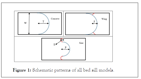
Figure 1: Schematic patterns of all bed sill models.
Numerical simulation
Package software was used to compute the flow pattern around the bed sill. The topographical dimensions of scouring pattern were transferred to software. Then the model was imported to package software. In order to prepare flow model geometry and applied to generate the computational mesh was used package software. To reduce computing time, only a part of the channel was simulated. Figure 2 presents a sample for one type of bed sills [6].
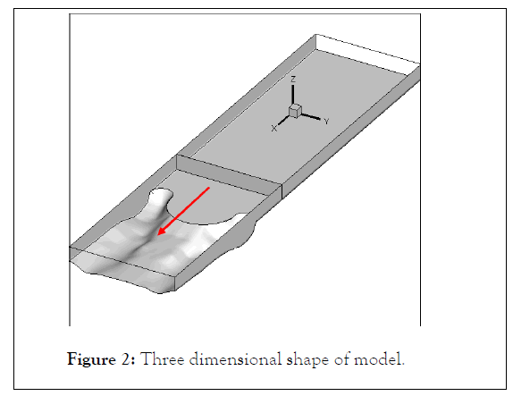
Figure 2: Three dimensional shape of model.
Studies were made the impact of shape and adjustment of bed sills on the bed and bank scouring at the downstream of the bed sills. The measurement of bed scouring at the downstream of bed sills showed that the maximum amount of scouring at the bank of the channel occurred by concave bed sill whereas the convex bed sill had the maximum amount of scouring.
Results and Discussion
The three dimensional pattern of bed scouring and also the contour lines of scouring at the downstream of the bed sill models are presented in Figure 4. According to the results of experimental study, it was concluded that not only the pattern of the bed scouring and maximum scouring occurred in very different scheme but also the scouring holes were created at different locations in the bed sill models. Figure 3 shows the comparison between different types of bed sills at variable distances of 0.35, 0.15 and 0.05 meters from the banks. It was concluded that with the concave bed sills produced maximum scouring at the banks [7]. According to the Figure 3, the maximum amount of scouring was found near the banks of concave bed sill while its location was at 0.15 m distance from the bank in sine bed sill. Furthermore, in the wing bed sill, maximum depth of scouring occurred at 0.11 m distance from the bank. Furthermore, type of bed sill depends on the type of challenge that must be considered. Based on the results of this study, maximum and minimum scouring depths were produced by concave and wing bed sills, respectively. In all three bed sills the minimum scouring depths were observed in the middle section of the channel. Among the three bed sill configurations, sine and wing shape sills had stabilized both bank and middle sections [8].
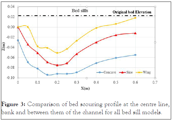
Figure 3: Comparison of bed scouring profile at the centre line, bank and between them of the channel for all bed sill models.
The sine bed sill can protect bed and banks of a channel from the erosion. The numerical analysis indicates that the maximum scouring depth location is between the wall and centre of the channel. The numerical simulation of sine bed sill is examined by one model sine. Figure 4 illustrates the longitudinal section of velocity contours. The observation shows that the maximum scouring depth usually is located in the edge of concave and convex bed sill. The reason for this phenomenon is the interference of vortices with the same rotation at the common boundary of concave and convex bed sills. In general, it is shown that the sine bed sill can stabilize the side and centre of the channel by creating vortices at both zones of the channel [9].
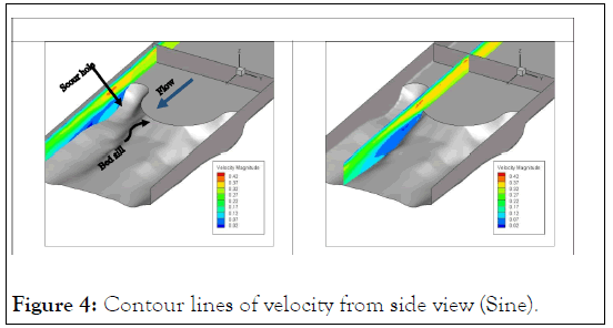
Figure 4: Contour lines of velocity from side view (Sine).
Furthermore, a plane of downstream flow of the bed sill is shown in Figure 5. According to results the vortices of banks transfer the sediments to the middle by their transition to the centre of the channel in the downstream of the bed sill. A major separation zone in downstream banks of the concave bed sill creates strong vortices. Therefore, maximum scouring depth occurs at the banks of the channel. Results also showed that the transition of vortices at the common boundary of the concave and convex bed sill towards the centre and transfer of sediments to the middle section. The observation shows that the maximum scouring depth usually is located in the edge of concave and convex bed sill. The reason for this phenomenon is the interference of vortices with same rotation at the common boundary of concave and convex bed sills. In general, it is shown that the sine bed sill can stabilize the side and centre of the channel by creating vortices at both zones of the channel. Results also show the vortices at the downstream of wing bed sills [10].
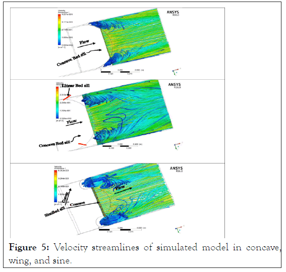
Figure 5: Velocity streamlines of simulated model in concave, wing, and sine.
Conclusion
The concave bed sill creates a major separation zone, scouring and vortices at the banks of the channel. The transfer of sediments to the centre is due to the shifting of the bank vortices to the central zone resulting in stabilization of the centre. However, the sine and wing shape bed sills are recommended to use when it is important to stabilize the banks and central section simultaneously. Since the vortices locations vary according to the types of the bed sill, the locations of vortices are mainly at both centre and side of the channel. In the middle section of the channel, minimum scouring was observed for the three types of bed sills. However, wing and sine shape bed sills could stabilize banks and bed sections more effectively than the concave bed sill. Among the three bed sills wing shaped had the maximum effect in reducing the scouring depth. Finally, the results showed that maximum and minimum scouring depths could be attributed to the concave and wing bed sills, respectively.
REFERENCES
- Gaudio R, Marion A. Time evolution of scouring downstream of bed sills. J Hydra Res. 2003: 41(3):271-84.
- Gaudio R, Marion A, Bovolin V. Morphological effects of bed sills in degrading rivers. J Hydra Res. 2000;38(2):89-96.
- Guan D, Melville BW, Friedrich H. Local scour at submerged weirs in sand-bed channels. J Hydra Res. 2016;54(2):172-184.
- Nik Hassan NMK, Narayanan R. Local scour downstream of an apron. J Hydra Eng. 1985;111(11):1371-1384.
- Hoffmans GJCM, Pilarczyk KW. Local scour downstream of hydraulic structures. J Hydra Eng. 1995;121(4):326-340.
- Keshavarzi A, Noori LK. Environmental protection stability of river bed and banks using convex, concave, and linear bed sills. Environ Monit Assess. 2010;171(1-4):621-631.
- Lenzi MA, Marion A, Comiti F, Gaudio R. Local scouring in low and high gradient streams at bed sills. J Hydra Res. 2002;40(6):731-739.
- Sohrabi M, Keshavarzi A, Javan M. Impact of bed sill shapes on scour protection in river bed and banks. Int J River Basin Manag. 2019;17(3):277-287.
- Sohrabi M, Keshavarzi A, Javan M. A study of flow structure topology in the vicinity of a concave bed sill using numerical model. Hydrology. 2020;8(2):26-33.
- Hagras MA, Agamy AF. The effect of downstream perforated blanket on the safety against piping in heading-up structures. Ain Shams Eng J. 2014;5(1):41-47.
Citation: Sohrabi M, Keshavarzi A (2021) Numerical and Experimental Study on the Effect of Curvilinear Bed Sill on Scour Protection. Single Cell Biol. 10:2.
Copyright: © 2021 Sohrabi M, et al. This is an open-access article distributed under the terms of the Creative Commons Attribution License, which permits unrestricted use, distribution, and reproduction in any medium, provided the original author and source are credited.
