Indexed In
- Genamics JournalSeek
- JournalTOCs
- CiteFactor
- RefSeek
- Hamdard University
- EBSCO A-Z
- OCLC- WorldCat
- Publons
- Google Scholar
Useful Links
Share This Page
Journal Flyer

Open Access Journals
- Agri and Aquaculture
- Biochemistry
- Bioinformatics & Systems Biology
- Business & Management
- Chemistry
- Clinical Sciences
- Engineering
- Food & Nutrition
- General Science
- Genetics & Molecular Biology
- Immunology & Microbiology
- Medical Sciences
- Neuroscience & Psychology
- Nursing & Health Care
- Pharmaceutical Sciences
Research - (2019) Volume 8, Issue 2
Modeling and Simulation of High-Performance Solar Thermoelectric Generator
Hadi Ali Madkhali1* and Ho-Sung Lee22Department of Mechanical Engineering, Western Michigan University, Kalamazoo, MI, USA
Received: 17-Jul-2019 Published: 18-Sep-2019
Abstract
A new and optimum design of a STEG has been developed for attaining an increased efficiency of 21.6%. The new design consists of three cascaded thermoelectric materials. In addition, it includes two glass panes, a selective solar absorber, two radiation shields, and forced air cooling system. The design is modeled theoretically and numerically using ANSYS software.
Nomenclature: Area of the absorber (Aa); The cross-sectional area of the thermoelectric elements (Ae); Cross sectional area of thermoelement (Ap, An); Optical concentration (Copt); Thermal concentration (Cth); Direct current (DC); Thermal conductivity (W/mk) (k); Thermal Conductivity for p-type and n-type (Kp, Kn); Leg length (L); Number of thermocouples (n); Heat flux (q); Rate of heat liberated at the cold junction (Qc); Rate of heat absorbed at the hot junction (Qb); Internal electrical resistance (R); Load resistance (RL); Internal electrical resistance for p-type and n-type (Rp, Rn); Solar thermoelectric generator (STEG); Thermoelectric generator (Teg); Voltage (V); Power output (W); Figure of merit with unit of (1/k) (Z); Seebeck coefficient with unit of (μV/K) (Α); Absorptivity (Αa); Junction temperatures (Th,c,1,2,3,4); Emissivity (Ε); Stefan constant (σ); Transmissivity of the glass (Τg); Thomson coefficient (τ); Electrical resistivity (Ω cm) (ρ)
Keywords
New modeling; Simulation; Optimization; Solar thermoelectric generator
Introduction
Solar thermoelectric generator (STEG) is one of the inventive renewable energy techniques which use the solar energy as a way of generating electricity. This device can be defined as a solid-state heat engine that converts sunlight directly into direct current (DC) electricity through the thermoelectric effects. The STEGs are featured with time stability, no vibration, no moving parts, and low scale systems [1-5].
In 1954, Maria Telkes reported the STEG system efficiency of 3.35% using flat plate collectors, a concentrating optical lens of 50 times, and a thermocouple made of zinc antimony (ZnSb) and bismuth antimony (BiSb). The efficiency was insufficient and not surpassed until 2011 [2,3]. In 2011, Daniel Kraemer demonstrated a promising flat-panel solar thermal energy-to-electric power conversion method, based on the Seebeck effect and high thermal concentration without any optical concentrators. The STEG cells made of nanostructured thermoelectric materials, a flat-panel selective absorber, and two bottom electrodes that serve as heat spread and radiation shields. The device is surrounded by a glass enclosure maintaining an evacuated environment. The developed STEG reached a peak efficiency of 4.6%. This approach consisted of a highly solar-absorbing surface that converts the solar radiation into heat, and thermally concentrates the thermoelectric elements by means of lateral conduction. Recently, Kraemer reported another experiment result of STEG with efficiency of 7.4%. He reached to this performance by adding a high optical concentration and segmented thermoelectric legs [3,6].
By utilizing an incident flux of 100000 W/m2 with a hot side temperature of 1000°C, Baranowski predicted theoretically that a STEG could achieve efficiency of 15.9%. Also, he recognized that using a STEG with ZT=2 at 1500°C would have an efficiency of 30.6% [3,7].
In 2014, Chang investigated the performance of the STEG by simulating three different geometries of thermoelectric generators at a constant leg length. This work found that the maximum system efficiency of 4.15% was produced by the smallest cross-sectional area of the elements. Chang’s paper indicates that decreasing the cross-sectional area of the thermoelectric element at a given element length will assist to improve the performance because the thermal concentration (Cth) goes up [3,8]. The thermal concentration is defined as the area ratio of the solar absorber to the cross-sectional area of the thermoelectric elements. Olsen developed a STEG prototype using high optical concentration (200-300 suns) for achieving high junction temperature of 1000°C. They reached a total efficiency of 15% using a selective solar absorber coating that allow for high absorbance over the solar spectrum while inhibiting emittance of the blackbody spectrum at 1000°C. The device includes a thermally insulating cavity that allows concentrated sunlight to enter through a small aperture at the top of the cavity [9].
The radiative loss from the hot surface of STEG was not a significant loss mechanism at the earliest time since the devices were operated at such low temperatures. Recently, TEG modules are optimized to operate at hot side temperatures of 1000°C [10]. As a result, at high temperatures, there will be high emissivity that causes radiation losses if the system is not engineered properly. The method for controlling radiation loss is to design the optical properties of the absorber material to allow absorption in the visible region of the spectrum in which the majority of the incident solar flux is concentrated but to suppress emission at longer wavelengths that correspond to the blackbody spectrum of the absorber [11,12]. This issue can be resolved using a selective absorber with energydependent absorptivity/emissivity. In an ideal selective absorber, the absorptivity takes the form of a step function, in which the step from one to zero is located between the solar flux and blackbody maxima. The location of the step edge is referred to as the cutoff wavelength. The optimum cutoff wavelength is a function of both the temperature and optical concentration [13]. The heart of the solar collector is the absorber: the heater component of the solar collector. Absorber plates are usually made of metal such as copper, aluminum and steel because they are good heat conductors. Copper is the most expensive but also the best conductor and corrodes less than aluminum. As the absorber warms up to a temperature higher than the ambient temperature, its emissivity goes up. In order to reduce energy loss through heat emission, the most efficient absorbers have a selective surface coating. The coating is a material with high absorbance and low emittance properties applied to or on the surface of solar absorbers. The usual coatings provide a degree of absorption of over 90%. The efficient solar absorber must have high solar absorbance and a low thermal emittance at the operational temperature [14-25]. To produce such coatings, one should consider combining different materials; developing multilayers; and adjusting various parameters such as the material’s composition, their thickness, and structure at the nanoscale, among others. There are several ways of fabricating selective solar absorbers. The most commonly developed materials, which operate with high temperature up to 1000°C, are metal-dielectric composites (cermet) and multilayers [14,15,18-20,22-24,26].
Considering all of the above studies and works, a new and optimum design of a STEG has been developed for attaining an increased efficiency of 21.6%. The new design consists of three cascaded thermoelectric materials. In addition, it includes two glass panes, a selective solar absorber, two radiation shields, and forced air cooling system. The design is modeled theoretically and numerically using ANSYS software.
Research Methodology
Components of the new design
The STEG has a concentration lens, two glass panes, one selective absorber, and two radiation shields between the hot and cold junctions. As shown in Figure 1, three different thermoelectric materials are cascaded and each one is optimized in conjunction with other cascades for the maximum power output and efficiency by an optimal design concept using the dimensional analysis illustrated previously. In addition, forced air on a heat sink for the cooling purpose of the cold junction is applied in this model. Table 1 can illustrate the main design differences between this new prototype and the STEG designs presented in literature:
In order to solve the model theoretically, the temperature of the absorber and the conductor is assumed to be uniform. Also, the temperature of cold junction with ceramic plate and the base of heat sink are assumed to be uniform too. The overall fin efficiency takes care of the thermal resistance between the plates. There is no convection loss inside the unit due to evacuation. The thermoelectric materials are temperature-independent since we use an average for the range of operating temperatures.
| Authors | Work Type | Material | ΔT | Optical Concentration Cop | Thermal Concentration Cth | STEG η,% | Comment |
|---|---|---|---|---|---|---|---|
| Maria Telkes | Experiment | ZnSb /BiSb | 247 | 50 | 1 | 3.35 | |
| Kraemer et al. | Experiment | Bi2Te3 | 180 | 1 | 299 | 4.6 | |
| Kraemer et al. | Experiment | Segmenting two thermoelectric materials, skutterudite and bistmuth telluride | 575 | 200 | 1.4 | 7.4 | |
| Baranowski et al. | Theoretical | Today’s materials (ZT=1) | 900 | 100 | - | 15.9% | |
| Baranowski et al. | Theoretical | Today’s materials (ZT=2) | 1400 | 100 | - | 30.6% | |
| Chang et al. | Simulation using ANSYS software | bismuth telluride | - | - | 253.13 | 4.15 | They tested numerically three different sizes of thermoelectric element made of bismuth telluride. They found that the smallest element gives the best performance. |
| Olsen et al. | Experiment | Segmented materials | 800 | 200-300 | - | 15 | Their prototype of STEG included solar-selective absorber coating with high absorption over the solar spectrum while inhibiting emittance of the blackbody spectrum at 1000 °C. Also, The STEG prototype includes a thermally insulating cavity that will allow concentrated sunlight to enter through an aperture. |
| This Paper | Simulation using ANSYS software | Three Cascaded Materials (SnSe, PbTe, and BiTe) |
892.83 | 30 | 60 | 21.6 | The STEG has a concentration lens, two glass panes, one selective absorber, and two radiation shields between the hot and cold junctions. |
Table 1: The main design differences between this new prototype and the STEG designs presented in literature.
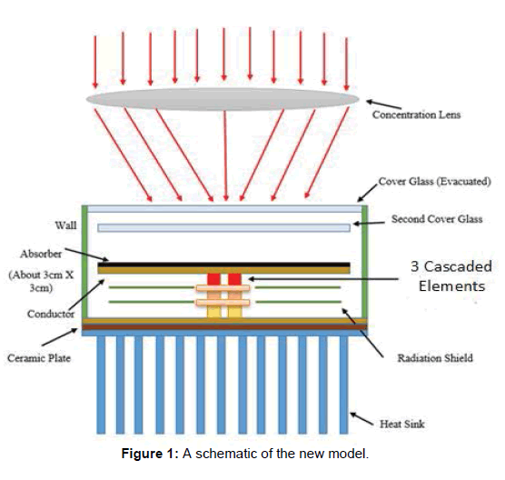
Figure 1: A schematic of the new model.
Analysis and input data
In this new design, the optical concentration is 30 suns and the solution will be based on the 1.5 G condition. The model can be divided into three main parts, solar collector, thermoelectric generator, and cooling system. The first system will include two cover glasses and solar absorber. Dimensions and parameters of the first system are given in the following Table 2.
| Symbol | Definition | Value |
|---|---|---|
| qs” | Solar flux | 1000 W/m2 |
| T8,c | Surrounding temperature | 20°C |
| hg | Convection coefficient on glass | 2 W/m2K |
| eg | Emissivity of the glasses | 0.1 |
| tg | Transmittance of glasses | 0.94 |
| Aa | Area of absorber | Aa=2AeCth |
| aa | Absorptivity of absorber | 0.95 |
| ea | Emissivity of absorber | 0.1 |
Table 2: Dimensions and parameters of the solar collector.
The second system is the thermoelectric generator which consists of three cascaded elements. The following graph in Figure 2 shows dimensions and properties of each element:
From the above Figure 2, Le represents the leg length in mm, Ae is the cross section area of thermoelement, α is Seebeck coefficient, ρ is electrical resistivity, and k is thermal conductivity. Note that subscript p indicates to p-type while subscript n indicates to n-type. In addition, emissivity of hot and cold junction temperatures are ε1=0.1 and ε2=0.1.
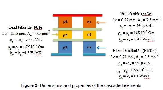
Figure 2: Dimensions and properties of the cascaded elements.
Then, the cooling system in this design will be forced convection cooling using extended surfaces with an air ambient temperature of 20°C.
In order to solve the model using the given data, we need to analyze the system. From Figure 3, the heat balance at the top glass, which is defined in this paper as glass number 2, and can be expressed as:
 (1)
(1)
The first part in the above equation represents radiation heat transfer between the two glasses; the second part is the radiation loses from the top cover glass, which is glass number 2, to the surrounding. The last part in the above equation is convection loses from the top glass to the surrounding.
Aa is already defined previously as a solar absorber area; εg1g2 is the net emissivity between the glasses; σ is Steven constant; Tg2 is temperature of cover glass number 2; Tg1 is temperature of cover glass number 1; T∞ is an ambient temperature; and h is the convection coefficient on the top glass.
Now, let us go to glass number 1 and get the heat balance equation. From Figure 3, the heat balance equation can be written as,
 (2)
(2)
The first part in this equation is the radiation heat transfer to the absorber, and second part is the radiation heat transfer to the top glass.
εag1 is the net emissivity between glass number 1 and the absorber.
From Figure 3, the heat balance at the absorber is written as,
 (3)
(3)
The ideal equations of the thermoelectric generator for the cascaded elements are,
 (4)
(4)
 (5)
(5)
 (6)
(6)
 (7)
(7)
 (8)
(8)
 (9)
(9)
From Figure 3, the heat balance at the cooling system is,
 (10)
(10)
The STEG is consisting of three cascaded elements, so the current for each stage can be written as,
 (11)
(11)
 (12)
(12)
 (13)
(13)
Applying the dimensionless concept which is provided by Dr. Lee [1] for the thermoelectric generator in conjunction with heat sinks in order to optimize the STEG is one of the important goals of this work. This theory (analysis) can help to maximize performance of the TEG and then the STEG by simultaneously optimizing the load resistance and geometry of the thermocouple. The dimensionless parameters of the solar thermoelectric generator such as load resistance ratio Rr, conductance Nk, and convectance Nc can be examined in order to improve the performance of the STEG model. Based on Figure 3, the heat balance equations have been created. In order to build dimensionless parameter for this system, each part in the equations from 1 to 10 is divided by the solar absorbed by the absorber (Qabs) because this value is constant. The STEG includes designing of a cooling system using rectangular fins in order to keep the cold junction temperature below 38°C. Air of ambient temperature 20°C enters a heat sink made of aluminum at velocity 1 m/s. The convection coefficient in the heat sink is 20 W/m2 K. Not only designing the forced convection multiple fins are considered in this model, but also optimizing the heat sink.
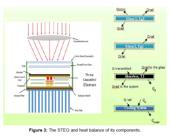
Figure 3: The STEG and heat balance of its components.
Theoretical Results and Discussion
At the beginning, we will see the optimal absorber area which can be calculated using the relation form Table 1, Aa=2AeCth By solving equations from (1) to (13) and applying the dimensionless concept, we can get Figure 4, As it is shown from the above Figure 4 that the maximum efficiency of the STEG can be attained at Cth=60. Then, the absorber area that we need is 9 cm2. Using this area and the equations from 1 to 13, we can be able to calculate the power output and the STEG efficiency as functions of the dimensionless parameters (Nk1, Nk2, Nk3) as following,
Figures 5-7 plot the power output and STEG efficiency versus dimensionless Nk. Results of the graph of Figure 5 when (Nk) for the first cascaded elements varies from 0.1 to 10. As we see from the graph that the maximum power output and maximum STEG efficiency occur at Nk1=0.3. The thermal conductance (K) can be calculated using the following relation,
Nk=(k A)/L
we can get the optimum value for both leg length and cross section area of the first cascaded element (SnSe). These optimum values can achieve the maximum power output and the maximum STEG efficiency. The same steps are following for other cascaded elements (PbTe, and BiTe) in order to optimize the system. Using Mathcad software, simultaneously, we can get the optimum leg length and cross section area of each thermocouple.
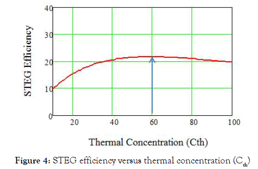
Figure 4: STEG efficiency versus thermal concentration (Cth)
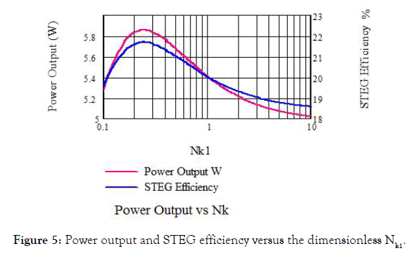
Figure 5: Power output and STEG efficiency versus the dimensionless Nk1.
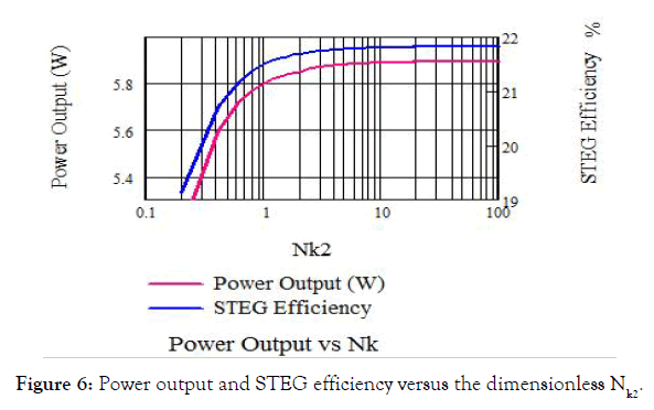
Figure 6: Power output and STEG efficiency versus the dimensionless Nk2.
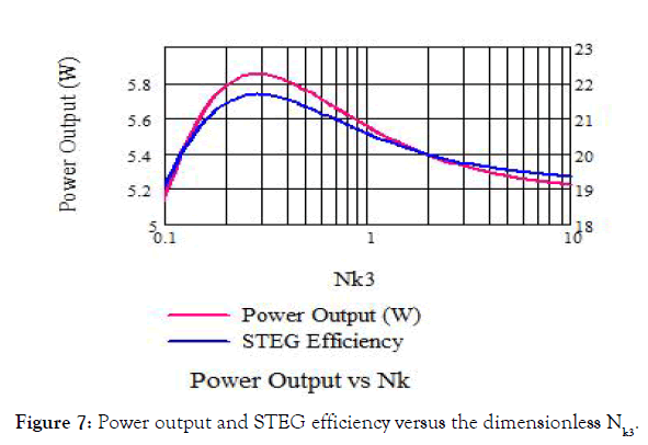
Figure 7: Power output and STEG efficiency versus the dimensionless Nk3.
Numerical work
The STEG design is simulated using ANSYS software. The simulation is 3D using Fluent and thermal-electric systems. As has been explained, the STEG system consists of two glasses, absorber, three cascaded thermoelectric materials, two radiation shields, and heat sink. In addition, fluid domain for the cooling system has been created. All of these parts can be created in 3D using ANSYS DesignModeler, as shown in Figure 8. The STEG is enclosed in a vacuum.

Figure 8: The STEG model in 3D.
The following Figure 9 shows the temperature distribution in 3D for the STEG. The temperature is displayed in units of Kelvin.

Figure 9: The temperature distribution of the STEG.
In order to get the power output of the STEG, Fluent’s results have been transferred to thermal-electric system using a coupling tool. Figure 10 shows the temperature distribution of the cascaded thermoelectric elements. As it is shown in the figure that the hot junction temperature is 930.93°C and the cold junction temperature is 38.1°C. The temperature difference is 892.83°C.
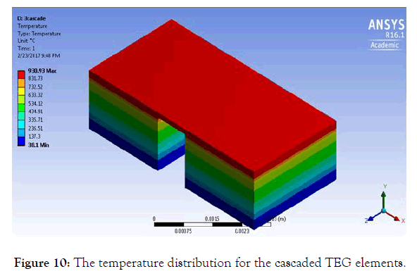
Figure 10: The temperature distribution for the cascaded TEG elements.
Contact resistances
The thermocouples are usually connected in series by highly conductive metal strips. A number of thermocouples are connected electrically in series and sandwiched between ceramic plates. These conductors add electrical and thermal resistances to the system, which sometimes increase the discrepancies between the realistic and ideal equation models. Therefore, another simulation of the cascaded elements including the contact resistances will be considered. In this section, we are comparing the theoretical and numerical solutions. In addition, as we see from the Figures 11, 12, and 13 that we are comparing two kinds of solutions. The blue solid points are the solution that does not include the contact resistances between the cascaded TEG elements while the red solid points include the contact resistances. Figure 11 shows the power output (watt) versus the load resistance ratio for the first cascaded element which is Tin Selenide (SnSe). Simulation the STEG was based on the optimum value of the load resistance ratio which gives the maximum power output. Figures 11-13, show the power output (watt) versus the load resistance ratio for the other cascaded materials PbTe and BiTe. After simulated the STEG based on the optimum values, we achieved the promising STEG efficiency of 21.6% with power output of 5.7 W.

Figure 11: Power output versus load resistance ration of the first cascaded elements.
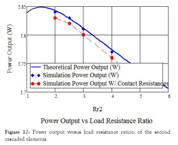
Figure 12: Power output versus load resistance ration of the second cascaded elements.

Figure 13: Power output versus load resistance ration of the third cascaded elements.
The above Tables 1-3 shows comparison between theoretical and simulation results. Based on the above table, there are small errors; for example the error between the two results for the heat absorbed by the absorber is 1.17%.
| Variables | Qabs, W | T1, C | T2, C | T3, C | T4, C | T1g, C | T2g, C |
|---|---|---|---|---|---|---|---|
| Theoretical Results | 24.1 | 932.85 | 533.599 | 466.229 | 37.861 | 776.85 | 478.088 |
| Simulation Results | 23.821 | 930.93 | 536.85 | 465.2 | 38.1 | 775.41 | 479.03 |
Table 3: Comparison between theoretical and simulation results.
Conclusion
The new design of STEG in this paper consists of a selective solar absorber, high transmissivity of glasses, three different thermoelectric materials employing 30 suns. The design has been analyzed theoretically. And the model has been numerically examined using a Solar Load Model Tracing tool by ANSYS software. Using a selective solar absorber with absorptivity of 0.95 and emissivity of 0.1, optimized the TEG, cooling system, the new STEG achieved efficiency of 21.6% with Power output of 5.7 W.
REFERENCES
- Lee HS. Thermoelectrics: Design and materials. Wiley, Chichester, UK. 2017.
- Telkes M. Thermoelectrics: Design and materials. Journal of Applied Physics. 1954;25:765.
- Madkhali HA, Hamil A, Lee H. Validation, optimization and simulation of a solar thermoelectric generator model. Journal of Electronic Materials. 2017;46:6756.
- Kraemer D, Poudel B, Feng HP, Caylor JC, Yu B, Yan X, et al. High-performance flat-panel solar thermoelectric generators with high thermal concentration. Nature Materials. 2011;10:532.
- Kraemer D, Mcenaney K, Chiesa M, Chen G. Modeling and optimization of solar thermoelectric generators for terrestrial applications. Solar Energy. 2012;86:1338.
- Kraemer D, Jie Q, Mcenaney K, Cao F, Liu W, Weinstein LA, et al. Concentrating solar thermoelectric generators with a peak efficiency of 7.4%. Nature Energy. 2016;1:16153.
- Baranowski LL, Snyder GJ, Toberer ES. Concentrated solar thermoelectric generators. Energy & Environmental Science. 2012;5:9055.
- Chen WH, Wang CC, Hung CI, Yang CC, Juang RC. Modeling and simulation for the design of thermal-concentrated solar thermoelectric generator. Energy. 2014;287–297.
- Olsen M, Warren E, Parilla P, Toberer E, Kennedy C, Snyder G, et al. A high-temperature, high-efficiency solar thermoelectric generator prototype. Energy Procedia. 2014; 49:1460.
- Weidenkaff A, Trottmann M, Tomeš P, Suter C, Steinfeld A, Veziridis A. Solar TE converter applications. Thermoelectric Nanomaterials. 2013;365.
- Ong K. Reverse flow in natural convection heat pipe solar water heater. International Journal of Low-Carbon Technologies. 2015.
- Moraes FS, Santos LC, Alencar RN, Sempels ÉV, Sandoval JCV, Lesage FJ. Solar thermoelectric generator performance relative to air speed. Energy Conversion and Management. 2015;99:326.
- Baranowski LL, Warren EL, Toberer ES. High-temperature high-efficiency solar thermoelectric generators. Journal of Electronic Materials. 2014;43:2348.
- Valleti K, Krishna DM, Reddy PM, Joshi SV. High temperature stable solar selective coatings by cathodic arc PVD for heat collecting elements. Solar Energy Materials and Solar Cells. 2016;145:447.
- Pérez IH. Multilayer solar selective coatings for high temperature solar applications: From concept to design, Thesis. 2016.
- Sergeant NP, Agrawal M, Peumans P. Design of selective coatings for solar thermal applications using sub-wavelength metal-dielectric structures. Optical Modeling and Measurements for Solar Energy Systems III. 2009.
- Sharma M, Sharma CL, Haokip D. Anatomical and physical characteristics of some rattan species. Indian Acad Sci. 2015;15:132-139.
- Bass M. Handbook of optics. Applications of Non-linear Fiber Optics. 2001.
- Nuru Z, Kotsedi L, Arendse C, Motaung D, Mwakikunga B, Roro K. Thermal stability of multilayered Pt-Al2O3 nanocoatings for high temperature CSP systems. Vacuum. 2015;120:115.
- Nuru ZY. Spectrally selective alxoy/pt/alxoy solar absorber coatings for high temprature solar-thermal applications. Thesis. 2014.
- Mammadov F. Study of selective surface of solar heat receiver. International Journal of Energy Engineering. 2012;2:138.
- Shimizu M, Akutsu H, Tsuda S, Iguchi F, Yugami H. A high-temperature solar selective absorber based upon periodic shallow microstructures coated by multi-layers using atomic layer deposition. Photonics. 2016;3:13.
- Bichotte M, Dubost L, Pouit TA, Soum-Glaude AL, Gal H. Glenat A. Arc deposited Ti-AlN selective absorber for high temperature CSP applications. Itskhokine. 2016.
- Gray M, Tirawat R, Kessinger K, Ndione P. High temperature performance of high-efficiency, multi-layer solar selective coatings for tower applications. Energy Procedia. 2015; 69,398.
- Bermel P, Lee J, Joannopoulos JD, Celanovic I, Soljacie M. Selective solar absorbers. Annual Review of Heat Transfer. 2012;15:231.
- Vijaya RSKG, Muralidhar SM, Srinivas MR, Satyanarayana BS. Development, analysis of tungsten-aluminium oxide based solar thermal multilayer coating. International Journal of Chem Tech Research. 2015.
Citation: Madkhali HA, Lee HS (2019) Modeling and Simulation of High-Performance Solar Thermo-Electric Generator. J Appl Mech Eng. 8:320. doi: 10.35248/2168-9873.19.8.320
Copyright: © 2019 Madkhali HA, et al. This is an open access article distributed under the term of the Creative Commons Attribution License, which permits unrestricted use, distribution, and reproduction in any medium, provided the original author and source are credited.
