Indexed In
- Open J Gate
- JournalTOCs
- RefSeek
- Hamdard University
- EBSCO A-Z
- OCLC- WorldCat
- Scholarsteer
- Publons
- Geneva Foundation for Medical Education and Research
- Google Scholar
Useful Links
Share This Page
Journal Flyer

Open Access Journals
- Agri and Aquaculture
- Biochemistry
- Bioinformatics & Systems Biology
- Business & Management
- Chemistry
- Clinical Sciences
- Engineering
- Food & Nutrition
- General Science
- Genetics & Molecular Biology
- Immunology & Microbiology
- Medical Sciences
- Neuroscience & Psychology
- Nursing & Health Care
- Pharmaceutical Sciences
Research Article - (2023) Volume 11, Issue 4
Gradient Magnetic Field of MR Scanners
Zeljko D. Vujovic*Received: 17-Jan-2023, Manuscript No. MCA-23-19588; Editor assigned: 20-Jan-2023, Pre QC No. MCA-23-19588 (PQ); Reviewed: 03-Feb-2023, QC No. MCA-23-19588; Revised: 17-Apr-2023, Manuscript No. MCA-23-19588 (R); Published: 24-Apr-2023, DOI: 10.35248/2329-6798.23.11.427
Abstract
The topic of this paper is parts of modern MR devices, in which the magnet windings are located. MR scanner magnets are made of four types of electromagnetic windings: The main magnet, made of superconducting material, creates a variable magnetic field; X coil, made of resistive material, creates a variable magnetic field, horizontally, from left to right, across scanning tube; Y coil creates a varying magnetic field, vertically, from bottom to top; Z coil creates varying magnetic field, longitudinally, from head to toe, within scanning tube. Superconductors, which create the main magnetic field, should be cooled by liquid helium and liquid nitrogen. Main magnets made of superconductors should use cryostat, with cooling vessels with liquid helium and liquid nitrogen, thermal insulation, and other protective elements of the magnet system. The types of magnets that exist in the basic configurations of MR scanners are analyzed. Scanners in the form of a closed cylindrical cavity create their own, magnetic, fields by passing a current through the solenoid, which is held at the temperature of the superconductor. The superconductors used exclusively are Niobium-Titanium (NbTi), Niobium-Tin (Nb3Sn), Vanadium-Gallium (V3Ga), and Magnesium-Diboride (MgB2). Only magnesium diboride is a high temperature superconductor, with a critical temperature of Tc=39°K.
The three remaining superconductors are low temperatures. New high-temperature superconductors have been discovered, as well as room-temperature superconductors. Newly discovered superconducting materials are not used in MR scanners. The magnet structure of the MR scanner is complex. The resonant frequency changes at each point of the field in a controlled manner. The windings of the main magnet made of superconducting material in the form of microbial fibers are built into the copper core. The nonlinear gradient field is created by windings of conductive material. It is added to the main magnetic field. Thus, the resulting magnetic field is obtained.
Keywords
Magnets; MR scanners; Cryostat; Superconductors; Gradient windings
Introduction
An experiment, in which nuclear magnetic moment was measured very directly, was described in 1938. The basic homogenous magnetic field was sufficiently strong to decouple completely the nuclear spins from one to another and from nuclear rotation. A small oscillating magnetic field was applied at right angles to a much larger constant field. A re-orientation of the nuclear spin and magnetic moment concerning the constant field occurred when the frequency of precession of the particular angular momentum vector was in question [1]. It was the first successful method of measuring nuclear magnetic moments in a complex magnetic field, produced by two sources, in this case.
The theory of superconductivity is presented, based on the fact that the interaction between electrons created by virtual phonon exchange is attractive when the difference in energy between the included electronic states is less than the phonon energy, hω. It is advantageous to form a superconducting phase when this attractive interaction dominates the repulsively screened coulomb interaction. The normal phase is described by the Bloch single-particle model. The theory gives a second-order phase transition and the Meissner effect in the form proposed by Pippard. The calculated values of specific heats and penetration depths and their temperature variations agree well with the experiment. There is an energy gap for individual particle excitations that decreases from about 3.5 kTc at T=0°K to zero at Tc. Tables of matrix elements of single particle operators between waves of superconducting excited states, useful for interference extensions and transition probability calculations, are given [2].
Paul Laterbur and Peter Mansfield received the Nobel Prize in medicine in 2003, “for discoveries related to the visual representation of magnetic resonance imaging”, thirty years after the publication of the results of Paul Laterbur's experiment. A graphical representation of these results, published on March 16, 1973, is shown in the next Figures. What are the structure and working principles of magnets used in modern MR scanners? It is an interesting and significant question, which deserves a comprehensive account [3].
The transverse gradient field is considered in the plane transverse to the longitudinal shape of the cylinder. It is added to the basic, strong, constant magnetic field, oriented along the long axis of the cylinder. It consists of three components: The "zgradient", a much smaller field than the basic one, in the longitudinal direction; “x-gradient”, field B such that ∂Bz/ ∂x=const; "y-gradient", field B such that ∂Bz/∂y=const. It is created by coils consisting of cylindrical coils and four sets of wound loops arranged in azimuthal and axial directions with respect to the axis of the cylinder.
Each set of loops has a surface current density, which is a vector quantity: λ(ϕ,z)=k•a•Ϭϕ(z)•cosϕϕ+k•a•Ϭz(z)•sinϕz. Ϭϕ(z) and Ϭz(z) are non-dimensional quantities in the space determined by the coordinates ϕ and z. ϕ is the unit vector in the azimuthal direction, and z is the unit vector in the longitudinal direction. The normalized plot of the z component of the magnetic field Bz, as a function of the transverse normalized component x/a, which is the radius of the cylinder, ideally shows a linear change of the field. In the real case, the graph is not linear. Reversal of direction when x is approximately equal to 0.7a. This nonlinearity limits the size of the object that can be recorded. Coils for transverse gradients are made by conventional etching methods in the form of continuous spiral patterns on a printed circuit board [4].
To create x and y-gradients in the static magnetic field H0, symmetrical golay coils are used. They are of identical construction, rotated by 900 relative to each other. In this way, a transversal magnetic gradient is obtained in two mutually normal directions. A symmetrical golay coil consists of four saddle coils. Each saddle coil is made of two incomplete arcshaped coils connected by conductors parallel to the z-axis. Arcshaped circular coils have a radius r centered on the z-axis. The arc of the winding covers an angle of 1200 [5]. Currents of the opposite direction flow through the conductors of the arcs. Arc windings are aligned parallel to the transversal x-y plane. In a typical installation there are multiple windings (e.g. 10) in each saddle winding. Pairs of saddle coils are electrically serially connected. The value of the x- and y-gradients depends on the position of the inner and outer arc along the z-axis. The contribution of the outer arc to the total gradient is negligible compared to the contribution of the inner arc. By bringing this arc closer to the inner one, the contribution increases, but slightly. The inner arcs of the golay coil are set at a standard distance of ± (z/r)=0.389, from the coordinate origin, along the z-axis, and the outer arcs are at a normalized distance of ± (z/ r)=2.57. The part of the body that is recorded is located at a predetermined "observation point", which is the beginning of the coordinate system [6].
Three mutually orthogonal windings to create a gradient magnetic field vary the z component of the main magnetic field along the x, y and z coordinate axes. Magnetic field gradients are defined as follows: Gx=∂Bz/∂x transverse magnetic gradient showing the variation of the z component of the magnetic field along the x axis; Gy=∂Bz/∂y transverse magnetic gradient showing the variation of the z component of the magnetic field along the y axis; Gz=∂Bz/∂z longitudinal magnetic gradient showing the variation of the z component of the magnetic field along the z-axis. The magnitude of the total magnetic field, equal to the z-component of the field, is given by the expression: Bz=B0 +xGx+yGy+zGz. As a consequence of Maxwell's equations, simultaneously with the generation of the gradient in Bz, two transverse components Bx and By are generated. They are called "accompanying fields" or "Maxwellian fields". By applying the gradient Gx, the accompanying component Bx=zGx of the gradient Gy, the accompanying component By=zGy of the gradient Gz, simultaneously two components Bx=(x/2)Gz and By=(y/2)Gz are generated. The homogeneity of the gradient is determined by the difference between the desired field B0(r) and the field actually achieved in the volume of interest B(r). The diameter of the spherical volume-DSV (Diameter of Sphere Volume) is defined as the diameter of the largest sphere within the gradient field error is not greater than a given percentage (e.g. 50%) of the value of the gradient field in the center of the sphere.
Windings for creating gradient magnetic fields are made as: Coils with individual windings, coils with distributed windings, coils with shielded windings and coils with windings in the plane. Spools from individual coils are made in the form of a ring or in the form of a seat. The idea of using a continuous current distribution on the surface of a cylinder is to obtain considerably larger usable values. Different methods have been developed for finding the optimal position for the multiple windings: Matrix inversion techniques, the “stream function” method, the target field approach, the harmonic minimization approach, the wave equation technique for compact gradient coils, momentum weighted conjugate gradient descent algorithm that uses a type of nonlinear constrained optimization, simulated annealing. The armor (shield) is placed between the gradient winding and the surrounding conductive structures. In this way, the gradient magnetic field outside the shield is cancelled. Without this shielding, the gradient magnetic field, which changes rapidly, would create eddy currents in the structures of the MRI system. Eddy currents would create their own magnetic fields, which would cause interference. The shield, in the form of a protective coil is in the form of a cylinder, placed around the primary cylinder. In that way, the inductive coupling with the environment is eliminated.
Flat gradient coils are made using target field, minimum inductance, wave equation and minimum power techniques [7].
MR scanner magnets are made of main magnet windings, gradient windings, and RF windings. The windings for the main magnets are made of superconducting materials and the windings for gradients and RF windings are made of resistant materials. The field created by the main magnet is necessary to bring the system of nuclear spins, on which it acts, to a state in which magnetic resonance is possible. The induction strength of the main magnetic field is the most important quantity for obtaining and for the strength of the magnetic resonance signal. Almost all modern MR scanners use a superconductor made of Niobium-Titanium (NiTi), which becomes superconducting below 94°K. Niobium-Tin (Nb3Sn), Vanadium-Galium (Va3Ga) and Magnesium-Diboride (MgB2) are also used. Only MgB2 is a high-temperature superconductor with a critical temperature of Tc=39°K. Nb3Sn is low temperature with Tc=183℃ and V3Ga low temperature with Tc=142℃.
The gradient system produces a calibrated distortion of the main magnetic field in the x, y or z direction (Figure 1). RF coils are responsible for perturbing the nuclear spin system, while patient coils are responsible for MR signal detection. New high temperature superconducting materials have been discovered as well as room temperature superconductors, (Tl5Pb2)Ba2Mg2Cu9O18+,Tc=28℃(310°K/55°K) and (Tl5Pb2) Bu2Mg2,5Cu8,5O17+, Tc=30℃(303°K/58°F) are given as an example. The hypothesis that main magnets could be made of high temperature superconductors and room temperature superconductors has not been proven (Figure 2). On the contrary, it has been shown that this is, for now, impossible because there are many difficulties in the application of newly discovered superconductors (instability in the magnetic field, low current density, the need to make high quality and extremely expensive materials). All practical solutions must be cooled at this time (Figure 3).
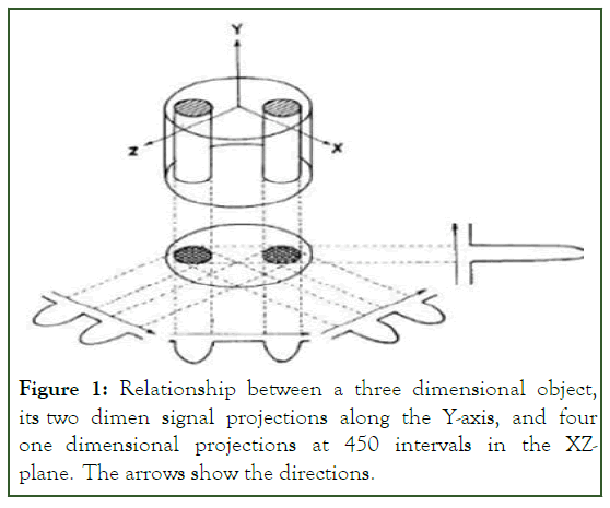
Figure 1: Relationship between a three dimensional object, its two dimen signal projections along the Y-axis, and four one dimensional projections at 450 intervals in the XZplane. The arrows show the directions.
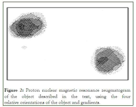
Figure 2: Proton nuclear magnetic resonance zeugmatogram of the object described in the text, using the four relative orientations of the object and gradients.
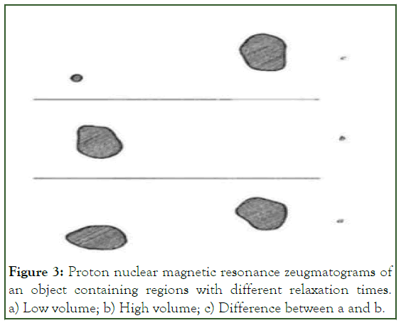
Figure 3: Proton nuclear magnetic resonance zeugmatograms of an object containing regions with different relaxation times. a) Low volume; b) High volume; c) Difference between a and b.
Materials and Methods
Main field (B0) coils (principal magnet windings plus superconducting shim and shield coils)-produce B0. Shim coils (to improve homogeneity). Gradient coils (for imaging, including their active shields) (Figure 4).
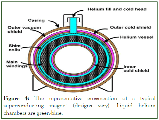
Figure 4: The representative cross-section of a typical superconducting magnet (designs vary). Liquid helium chambers are green-blue.
Radiofrequency (RF) body coil (transmits B1 field) (Figures 5-7). Patient coils (primarily to detect MR signal, some are transmitted/receive). A complete gradient system consists of coils mounted along the inner bore of the system (Figure 8). Produces calibrated distortion of the main magnetic field in x, y or z-direction, Radiofrequency (RF) coils (Figure 9).
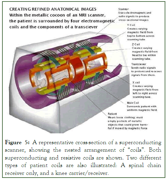
Figure 5: A representative cross-section of a superconducting scanner, showing the nested arrangement of “coils”. Both superconducting and resistive coils are shown. Two different types of patient coils are also illustrated: A spinal chain receiver only, and a knee carrier/receiver.
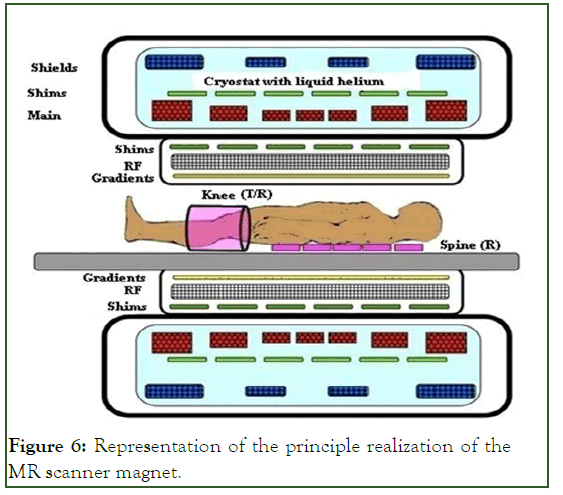
Figure 6: Representation of the principle realization of the MR scanner magnet.
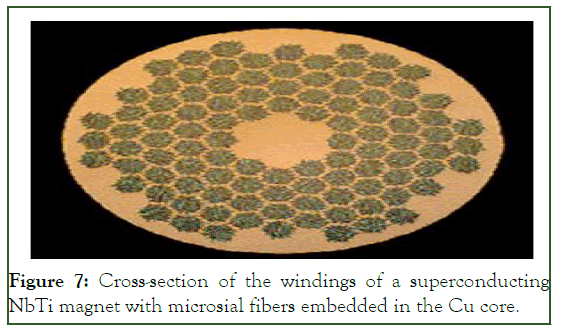
Figure 7: Cross-section of the windings of a superconducting NbTi magnet with microsial fibers embedded in the Cu core.
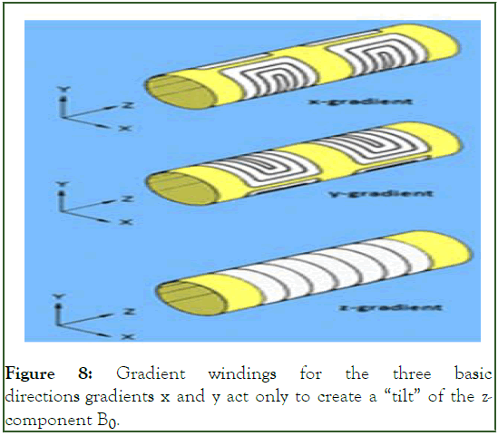
Figure 8: Gradient windings for the three basic directions gradients x and y act only to create a “tilt” of the zcomponent B0.
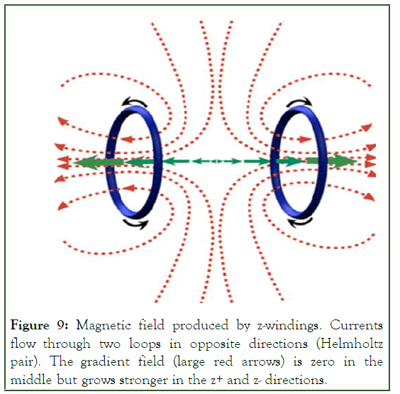
Figure 9: Magnetic field produced by z-windings. Currents flow through two loops in opposite directions (Helmholtz pair). The gradient field (large red arrows) is zero in the middle but grows stronger in the z+ and z- directions.
Results and Discussion
The Gradient (G) is defined as the change in field (ΔB) with respect to the change in distance ΔS, G=ΔB/ΔS. A gradient is a vector. It has magnitude and direction. The direction of the gradient is defined to match the direction of the main field.
Considering the field B, in the general case, as a vector field that has magnitude, direction and direction at each point of the field, the magnetic field, in the Cartesian coordinate system, can be expressed as: B=Bx i+By j+Bz k.
The gradient of the vector field B is denoted by B. It is a Jacobian or vector of the second order, a matrix of 9 partial derivatives of the main component of the field B (Bx, By, Bz) with respect to the three main directions (x,y,z). It is necessary to consider how each component of the field varies in each direction.
∂Bx/∂x ∂By/∂x ∂Bz/∂x.
J=∂Bx/∂y ∂By/∂y ∂Bz/∂z.
∂Bx/∂z ∂By/∂z ∂Bz/∂z.
In MR imaging, we assume the simplified case that the field B is directed completely in the direction of the z-axis (i.e. Bx=0 and By=0), with no change in the x- or y-directions. (All partial derivatives with respect to x- and y- are equal to zero.) The x-, y-, and z- gradients used for recording are considered to produce a variation of the B field with respect to the Bz component only. A good first order approximation is to consider only the partial derivatives in the third column of the Jacobian. All derivatives in the first two columns are assumed to be zero.
The gradients used for imaging are considered to distort the principal field B0 only with respect to the z direction. An x gradient, for example, just makes Bz stronger on one side of the scanner than the other.
Gradient windings are conductive loops of wire or thin conductive sheets on a cylindrical shell. The passage of current through these coils creates a secondary, gradient magnetic field. This gradient magnetic field slightly distorts the main magnetic field in a predictable way. It causes the resonant frequency of the proton to vary with position. The z-gradient design is based on circular Maxwell coils, and the transverse x, y-gradients on saddle-shaped golay coils. The x and y gradients only act to indicate the in-plane “warp” of the z-component plane B0.
The Maxwell pair of coils is a simplified variant of the original Maxwell version of three circular, coaxial coils, from which the central coil is omitted. According to Maxwell's original design, the central coil has a radius R and two side coils have a radius R√(4/7), located on either side of the main coil at a distance R√(3/7) from the central plane. The currents in the coils of the Maxwell pair have the same magnitude but opposite direction. The total field of a pair of coils can be expressed as the sum of the fields created by each coil separately. The coaxial center of the Maxwell pair of coils is the point z=0 and in it the magnetic gradient is Bz=0, but it increases in the +z and –z direction (Figure 10).
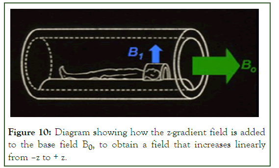
Figure 10: Diagram showing how the z-gradient field is added to the base field B0, to obtain a field that increases linearly from –z to + z.
The diagram in Figure 11 shows how the z-gradient field is added to the basic field B0 to produce a field that increases linearly from –z to +z. (→ B0, field alone+→z-gradient field= → static field increasing linearly along the z-axis).
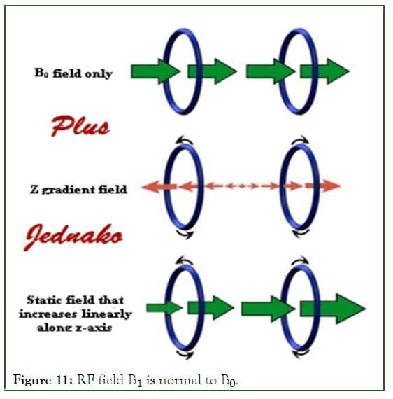
Figure 11: RF field B1 is normal to B0.
The design of transverse gradients in cylindrical MR magnets is based on a “double saddle” golay coil configuration. The simplest form of this set of coils consists of 4 inner and 4 outer arcs on the surface of the cylinder connected by 8 parallel z-axis conductors. The current through the internal arcs creates the required gradient. Conductors parallel to the z axis serve as current return paths. They do not contribute to the gradient field. The homogeneity of the golay configuration is improved by adding more arcs. The eight parallel z-axis conductors do not affect the z-component of the magnetic field (Bz). They produce the transverse components Bx and By, which are called "accompanying" or "Maxwellian fields". They should not be confused with x and y-gradients, which are spatial derivatives of Bz. Accompanying fields do not directly affect MR signal localization, but contribute to the total magnetic field experienced by the patient. The best performance of golay coils is achieved when each is 2.18r long, with a counter arc of 1200, and the inner margins are 0.78r apart.
Bio-Savar's law is the starting point for calculating the magnetic field created by the golay coil. Based on that law, the magnetic field strength vector created by a differential current element is inversely proportional to the square of the distance of that element from the point where the field is measured (dB=(μ0/4 π) Idlxr/r2). The origin of the coordinate system x,y,z is placed in the center of symmetry of the golay coil. At each observed point in the transverse plane, the magnetic field strength vector consists of three components directed in the x, y and z direction of the coordinate system. dB=dBxi+dByj+dBzk. In a simplified analysis, we consider the z component and its change in the direction of the x-axis. The first derivative of this component is the x-gradient. The goal is to make this derivative constant, (dBz/ dx)=const. In that case the x-gradient is linear. This was demonstrated experimentally in the work [8-12] Analogous to the x-gradient, the y-gradient (dBz/dy)=const is defined, with the fact that, for this gradient, the component of the magnetic field Bz created by the golay coil shifted by 900 u is observed relative to the coil that creates the x-gradient.
Proposal (Masfiled and Lauterbur): "Gradient" spatially encodes the positions of hydrogen nuclei within the sample, inducing variations in the Larmor frequency as a function of their position. The image with the terra 7 T Siemens healthcare magnet encouraged the work of this article [13].
MR scanner magnets are a set of three components: Main magnet, gradient magnets (x,y,z), and RF magnets. Together, they create the preconditions for magnetic resonance imaging to occur. In this set of magnets, the main magnet stands out in size and weight, which is made of superconductors, although the main magnet can also be made of permanent magnets and resistive conductors [14]. The other two components of the MR magnet system are made of resistive conductors.
To achieve the superconductivity of the material, which creates the main magnetic field, a crystal is used, with cooling vessels for liquid helium, thermal insulation, and other elements to protect the main magnet system. These elements determine the dimensions and size of the device. Initially, the helium should be replenished monthly. This was, gradually, perfected, so that liquid helium had to be replenished every 2-3 years. There are data that, lately, zero temperature cooling systems (ZBO) have become the standard.
In the case of a superconducting magnet, the power supply is connected on both sides of the coil segment. The current through the coil increases gradually, over several hours, until the desired field is reached. The current continues to flow in a closed loop, without a significant drop. The resulting property is that the magnetic field is always present [15-17]. The construction of superconducting magnets is considered to be extremely expensive, and cryogenic helium is expensive and difficult to maintain. Nevertheless, today they are the most common type of magnet found in MRI scanners. It is estimated that investing in the production of new usable superconductors would be a process that does not pay off.
The microbial fibers of one of the superconductors, NiTi, Nb3Sn, Va3Ga, or MgB2, are inserted into the copper conductors. Supports and protects alloy windings from damage provides mechanical strength and prevents deformations and vibrations. It takes over the conduction of electricity, if, due to a fault, the superconducting mode is lost (Quench).
A linear gradient is added to the main magnetic field, a balanced disturbance of the fundamental field along the axis of the magnet (x-side-side, y-front-back, z-head-heel). The crosssection of all three axes is the center of the magnet. In it, the basic magnetic induction has, always, the same value.
The construction of the z-gradient is usually based on circular coils, while the transverse(x-and y-) gradients typically have a saddle winding configuration. More precisely, the basic design of the z-direction gradient is Helmholtz's pair of coils: Two loops with currents flowing in opposite directions [18].
Helmholtz coils produce a gradually changing field, which is zero in the magnetic isocenter, but increases linearly outward, in both directions +z and -z. When this is added to the constant field B0, the result is a gradual increase in the gradient along the z-axis.
With the help of gradient windings, the value of the strength of the magnetic induction at each point of the three-dimensional space of the magnet is changed in a controlled manner. The resonant (Larmor) frequency is proportional to the strength of the magnetic induction. So, it has been achieved that the resonant frequency changes, controlled in every point of threedimensional space. This also means that the magnetic resonance signal is different at each point. The signal strength is proportional to the spin concentration at the observed point. By measuring the magnetic resonance signal, the concentration of spins in various parts of the sample can be determined [19].
The time-varying Radiofrequency Field (RF), used in MR, is denoted by B1. It must be normal to the main magnetic field B0. It is produced by special RF windings. RF windings can be transmitters, receivers, or both. If the oscillation B1 has a value close to the precession of the nuclear spins (Larmor frequency), the energy is deposited in the spin system, causing a change in its net magnetization. B1 is only switched on for short periods (several milliseconds), called "RF pulses". By adjusting the magnitude or duration of these B1 pulses, the nuclear spin system can rotate at variable angles of rotation, such as 90° and 180°.
A superconductor, unlike a conductor, conducts electricity indefinitely, without energy losses. This is an important characteristic of these materials and a challenge for their use. They do not lose electricity! For the main magnets of MR scanners are used: Niobium-Titanium (NbTi), Tc=10K, B0~15T (since 1960), Niobium-Tin (Nb3Sn), Tc=18,3°K 254.8℃/-426.7F), B0~25T to 30T (Since 1960), Vanadium- Gallium (V3Ga), Tc=14.2°K, B0~19T, Magnesium-Diboride (MgB2), Tc=39°K (-234℃/-389°F) (Since 2001). It can be noticed that out of four superconductors, three are low temperature and one is high temperature.
Professor Allen D. Elster states that there is, in the experimental phase, re-production of MR scanners using "high temperature" superconductors. An example is Magnesium-Diboride (MgB2), with a critical temperature Tc=39°K and others. He envisions the use of these superconductors, in the future, to build MR scanners. This was an incentive for digression from the main topic of this paper and a review of the current state and chronology of superconductors. It can be seen that a significant number of high temperature superconductors and room temperature superconductors were discovered. Their application in practice is far away. The question is whether and when these superconductors will be usable because of the properties they have. From the chronology of the discovery of superconductors, the following events can be singled out as markers: 1941. Niobium-nitride, Tc=160°K, 1945. Described perovskite, made the first commercial superconductor NbTi. At that time the use of Niobium Tin, Nb3Sn, began. In 1972, the BSC theory of superconductivity (Burden-Cooper-Schiffer) was described by MgB2.
This study confirmed, as important, that room temperature superconductors, although discovered, are not in the field of research of the world's leading laboratories, as possible materials for making magnets for MR scanners. Their indisputable discoveries are imposed, for research and application. The current situation is such that there is no known scientific method by which they could be turned into the useful, application, which should be eliminated. It is estimated that research to achieve this is extremely expensive. Scientific optimism gives hope that it is a matter of time before they become applicable and that the practical benefits of their discovery will be obtained.
Conclusion
This paper is important, primarily, because it explains the complex structure of the MR scanner magnet and how the resonant frequency changes in a controlled manner at each point of the magnetic field. The principle realization of the scanner, the cross-section of the windings of a superconducting magnet with microbial fibers, the principle of creating a nonlinear gradient and its role in creating the resultant magnetic field, the chronology of the discoveries in the field of high temperature superconductors, and room temperature superconductors are presented.
The paper emphasized the importance of the discovery of hightemperature superconductors and room-temperature superconductors, which were awarded Nobel prizes, but also the lag in the application of these discoveries for practical purposes. Objective reasons for this are given.
The initial assumption is that the main magnets of MR scanners are made of high temperature superconductors and room temperature superconductors have not been proven. On the contrary, it has been shown that these superconductors cannot be used to make the main magnets of MR scanners. This remains a possible idea for some future work, if and when, the newly discovered superconductors are brought to a practically applicable level.
Competing Interest
The author declares that he has no, financial competing interests. The author declares that he has no known nonfinancial competitive interests.
Author's Contribution
The conception, design, acquisition, analysis, and interpretation of data are, on the whole, the contribution of the author. This is, on the whole, individual research work.
The author agrees that issues related to the accuracy or integrity of any part, even those in which the author is not personally involved, should be investigated, and resolved and the resolution documented in the literature.
Acknowledgement
To Dejan Vujovic, an engineer for the development and maintenance of application software in the Montenegrin electricity transmission system Podgorica.
Availability of Data and Materials
All data generated or analyzed during this study are included in this published article and its supplementary files.
References
- Rabi II, Zacharias JR, Millman S, Kusch P. A new method of measuring nuclear magnetic moment. Phys Rev. 1938;53(4):318.
- Lauterbur PC. Image formation by induced local interactions: Examples employing nuclear magnetic resonance. Nature. 1973;242(5394):190-191.
- Bangert V, Mansfield P. Magnetic field gradient coils for NMR imaging. J Phys E: Sci Instrum. 1982;15(2):235.
- El-Sharkawy AM, Schar M, Bottomley PA, Atalar E. Monitoring and correcting spatio-temporal variations of the MR scanner’s static magnetic field. MAGMA. 2006;19(5):223.
[Crossref] [Google Scholar] [PubMed]
- Latta P, Gruwel ML, Volotovskyy V, Weber MH, Tomanek B. Simple phase method for measurement of magnetic field gradient waveforms. Magn Reson Imaging. 2007;25(9):1272-1276.
[Crossref] [Google Scholar] [PubMed]
- Moelker A, Wielopolski PA, Pattynama PM. Relationship between magnetic field strength and magnetic resonance related acoustic noise levels. MAGMA. 2003;16:52-55.
[Crossref] [Google Scholar] [PubMed]
- Momo F, Adriani O, Gualtieri G, Sotgiu A. Generalised Anderson coils for magnetic resonance imaging. J Phys E: Sci Instrum. 1988;21(6):565.
- Suits BH, Wilken DE. Improving magnetic field gradient coils for NMR imaging. J Phys E: Sci Instrum. 1989;22(8):565.
- Schaefer DJ, Bourland JD, Nyenhuis JA. Review of patient safety in time‐varying gradient fields. J Magn Reson Imaging. 2000;12(1):20-29.
[Crossref] [Google Scholar] [PubMed]
- Assecondi S, Vanderperren K, Novitskiy N, Ramautar JR, Fias W, Staelens S, et al. Effect of the static magnetic field of the MR-scanner on ERPs: Evaluation of visual, cognitive and motor potentials. Clin Neurophysiol. 2010;121(5):672-685.
[Crossref] [Google Scholar] [PubMed]
- Trakic A, Liu F, Lopez HS, Wang H, Crozier S. Longitudinal gradient coil optimization in the presence of transient eddy currents. Magn Reson Med. 2007;57(6):1119-1130.
[Crossref] [Google Scholar] [PubMed]
- Hidalgo‐Tobon SS. Theory of gradient coil design methods for magnetic resonance imaging. Concepts Magn Reson Part A. 2010;36(4):223-242.
- Zhang R, Xu J, Fu Y, Li Y, Huang K, Zhang J, et al. An optimized target-field method for MRI transverse biplanar gradient coil design. Meas Sci Technol. 2011;22(12):125505.
- Takahashi M, Uematsu H, Hatabu H. MR imaging at high magnetic fields. Eur J Radiol. 2003;46(1):45-52.
[Crossref] [Google Scholar] [PubMed]
- Farling PA, Flynn PA, Darwent G, de Wilde J, Grainger D, King S, et al. Safety in magnetic resonance units: An update. Anaesthesia. 2010;65(7):766-770.
[Crossref] [Google Scholar] [PubMed]
- Tamada D, Nakamura T, Kose K. A gradient coil design for a high-temperature superconducting bulk magnet using the finite-difference method. Supercond Sci Technol. 2015;28(9):095010.
- Trampel R, Mildner T, Goerke U, Schaefer A, Driesel W, Norris DG. Continuous arterial spin labeling using a local magnetic field gradient coil. Magn Reson Med. 2002;48(3):543-546.
[Crossref] [Google Scholar] [PubMed]
- Marques JP, Simonis FF, Webb AG. Low‐field MRI: An MR physics perspective. J Magn Reson Imaging. 2019;49(6):1528-1542.
[Crossref] [Google Scholar] [PubMed]
- Kim SJ, Kim KA. Safety issues and updates under MR environments. Eur J Radiol. 2017;89:7-13.
[Crossref] [Google Scholar] [PubMed]
Citation: Vujovic ZD (2023) Gradient Magnetic Field of MR Scanners. Modern Chem Appl. 11:413.
Copyright: © 2023 Vujovic ZD. This is an open access article distributed under the terms of the Creative Commons Attribution License, which permits unrestricted use, distribution, and reproduction in any medium, provided the original author and source are credited.


