Indexed In
- Open J Gate
- Genamics JournalSeek
- Academic Keys
- ResearchBible
- Cosmos IF
- Access to Global Online Research in Agriculture (AGORA)
- Electronic Journals Library
- RefSeek
- Directory of Research Journal Indexing (DRJI)
- Hamdard University
- EBSCO A-Z
- OCLC- WorldCat
- Scholarsteer
- SWB online catalog
- Virtual Library of Biology (vifabio)
- Publons
- Geneva Foundation for Medical Education and Research
- Euro Pub
- Google Scholar
Useful Links
Share This Page
Journal Flyer
Open Access Journals
- Agri and Aquaculture
- Biochemistry
- Bioinformatics & Systems Biology
- Business & Management
- Chemistry
- Clinical Sciences
- Engineering
- Food & Nutrition
- General Science
- Genetics & Molecular Biology
- Immunology & Microbiology
- Medical Sciences
- Neuroscience & Psychology
- Nursing & Health Care
- Pharmaceutical Sciences
Research - (2020) Volume 9, Issue 4
Design and Development of Zero till Rotary Cum Fertilizer Drill Coulter type Seed
K. Ramya1*, M. Lokesh1 and K. Ravi Chandra Charyulu22Post Graduate from, Vignan’s Foundation for Science, Technology and Research, Vadlamudi, Guntur, India
Received: 04-Sep-2020 Published: 19-Nov-2020, DOI: 10.35248/2168-9881.20.9.199
Abstract
A zero-tillage system is one of the farming methods that many scientists believe should be used by large and small farm holders to reduce gradual soil damage. Their research also showed that this method can improve the quality of life of farmers. This method has already been adopted by several countries. The purpose of this study was to develop and evaluate small farm owners' seed drill selection equipment with semi-rotating disc fertilizer towed by a tractor. The purpose of the machine is to cut off the remnants of previous plants and sow seeds at a set distance and seed depth. The research included the design, manufacture and testing of tractor-driven equipment, disc-type coulter cutters. We also compared traditional farming and conservation systems by collecting data from farmers through a questionnaire. The study found that using equipment could significantly reduce labor needs. In addition, the study showed that it would be economically feasible to use a zero-tillage farming system using equipment, assuming productivity is the same for conventional and conservative systems. As for adaptability. In addition, recommendations on equipment design have been made and some future directives have been declared.
Keywords
Zero tillage; Conventional tillage; Crop residues
Introduction
Farming systems can be divided into two systems: conventional farming systems (with intensive processing) and conservative farming systems. The conventional farming system consists of sawing, burning, pruning, furrowing, pre-emergence herbicides, planting, post-emergence herbicides and weeding or hand-threshing. While conservation soil treatment consists of mowing, application of herbicides, sowing, re-application of herbicides and manual weeding or howing.
Conservative agriculture does not interfere with soil conversion. Minimal soil disturbance leads to higher available soil moisture and greater groundwater reclamation potential with increased water infiltration rate and reduced evaporation from the soil surface. Minimal soil disturbance means less soil erosion (-58%), better soil structure and higher biological activity. Many farmers and scientists have realized that conventional agriculture has many negative effects on soil productivity, the environment and profitability. These farmers have tried and adopted some farming conservation practices and documented their benefits. Among the system of agricultural preservation now accepted by farmers worldwide is a zero-level tillage agricultural system.
Dr. Rolf Derpsh defines zero tillage as the process of planting a crop in unprepared soil by cutting off soil covered by crop residues and opening a narrow gap for seed placement at a suitable depth. Zero processing is based on three principles;
1. Minor soil disturbances,
2. Cover soil with plant residues for as long as possible
3. Crop rotation.
Zero yield is an agricultural system that is gaining popularity among many farmers around the world. Post-harvest straw is uneconomic and its end use is not yet widespread. Both residues are then applied to the soil or incinerated. The incorporation of straw into the soil has some advantages in improving soil fertility and yield. Studies have shown that zero-level farming systems can bring many benefits to farmers and the environment. Less work, more money, more erosion control and more respect for the environment and better quality of life are among the benefits of zero-level agriculture. Thanks to these advantages, zero-level agriculture has gained worldwide popularity. Other benefits of zero-tillage agriculture that cannot be challenged by intensive processing include reducing labor requirements, saving time, reducing machine wear, fuel economy, better long-term productivity, better surface water quality, reduced soil erosion, higher soil moisture retention, better water infiltration, reduced soil compaction, improved soil slope, reduced carbon emissions and reduced air pollution. As a result, the land covered by this agricultural system has increased in some parts of the world.
Although the zero-level agricultural system is one of the best agricultural systems identified by many farmers and scientists around the world, again many farmers, especially small farmers, have not even tried to prove it. It is claimed in the literature that scientists have identified some limitations to the introduction of agricultural zero. The first is the lack of farmers' knowledge of the agricultural system. According to a survey in Brazil, lack of technical knowledge and knowledge of the same farming method are the first two (2) reasons why farmers do not adopt an innovative farming system. The second is doubts about the agricultural system. Farmers are afraid to try it because they may not implement the technique correctly. Thirdly, there is a lack of agricultural machinery that is not available for processing, especially for small farmers.
Objective of the Study
The study specifically aimed to:
1. Selection of suitable coulter for cutting crop residues in field.
2. Design and Development of appropriate power transmission system for driving coulters
Review of Literature
In this study, they argued that the combination of rice and wheat is increasing rapidly in the Indigenous Plains (PGI) and that the loose straw behind the combine poses many management problems but can be harvested mechanically and used in many ways or crushed and distributed. Agricultural conservation in the countryside [1].
In this paper, they reported that zeroing to save planting time, fuel and water improves fertilizer efficiency, reduces weed density, reduces tractor wear, improves soil health, promotes waste management and helps reduce air pollution. [2].
Based on their research, they reported that several resource conservation technologies have been developed to improve the productivity and sustainability of the rice grain system without seriously endangering the natural resource base and the environment, which are popularized throughout the simple indogangetic [3].
in this study, they performed an inexpensive, manually operated, multicultural seed drill with an appropriate bucket size experiment in a bucket metering mechanism for a given culture. The drill was developed and evaluated in field conditions to study the characteristics and economic profitability of the seed model for small and small farmers in Odisha State [4].
In their study, they reported that the properties of the ocher seed model were soaked by various metered systems. The average spacing was close to the theoretical spacing for the vertical roll, horizontal plate (edge drop), with cell size 10% more than maximum seed size. In the case of a sloping plate, the mean distance was close to the theoretical distance with a cell size equal to the maximum seed size [5].
Developed and evaluated a conventional drill for sowing grain and oilseeds. The slanting bowl was divided into two partitions, separating the two types of seeds. The wheel speed ratioto the ground and the metering shaft is adjusted to minimize seed damage. Seeds were delivered at a rate of 3.75 kg / ha at a feed rate of 3 km / h and seed damage was only 3%. [6].
Materials and Methodology
This chapter deals with related theoretical research and equipment design.
Zero tillage farming is an agricultural process that involves managing soil fertility, intervening in the soil and making it cover the slaughtered mulches needed for planting / replanting. The main process is done by preparing cover crops followed by the plantation procedure, no other process is performed.
According to the Defense Technology Information Center (CTIC) and the National Association for Conservation Areas (NACD), a zero rate is an agricultural system where at least 30% of the residue remains after sowing and two-thirds of the rows are left undisturbed (Table 1).
| Diesel Fuel Use (Ltr/acre) | ||
|---|---|---|
| Maize | ||
| Conventional | Zero-Till | |
| Cultivate | 7 | 3.5 |
| Plant | 3.5 | 0 |
| Spray | 1 | 1 |
| Fertilize | NA | NA |
| Productivity | 1000 kg | 1050 Kg |
| Total | 11.5 | 4.5 |
Table 1: Fuel used in growing maize under Conventional and zero-till systems (No-Till Solutions).
Advantages of zero agriculture
Zero treatment has many agronomic advantages over conventional processing. Zero to significantly increase water infiltration, thus limiting soil erosion and improving water retention. In addition, soil conditions improve with increased organic matter content and better soil structure. Zero yields also increase soil moisture content, allowing farmers to plant at optimum dates.
Small farmers from different countries claimed to have a more stable and better income with zero cash. For this reason, the need for family work is reduced, so children can attend school and quality of life has improved.
Introduction of deposits worldwide
The farmer bought the farm in 1982, the land still has a barren form of soil typical of the great central savannas of Brazil. The farmer was deterred by rough terrain by buying 620 acres or 250 hectares of planting soybeans. The area has historically been considered unproductive. Then came the rainy season, flooding much of his first harvest. The following years brought rain again and again to wash the soil, seedlings and most of the promises of the new farm.
Zero - up to drill functionality
• Seeder is a machine for positioning seeds in a continuous flow in furrows at a constant speed and at a controlled depth with or without ground cover.
• Drills equipped with a fertilizer dropper spread the fertilizer evenly on the ground, called a fertilizer drill. , They simultaneously supply seeds and fertilizers according to an acceptable scheme. The seed fertilizer drill has a large seed box divided into two compartments, one for seed and one for spreading the fertilizer.
• The basic purpose of sowing is to place the seed and fertilizer in rows at the desired depth and seed spacing, to cover the seed with soil and to ensure proper seed compaction.
Seeding and fertilizer components
With the advent of zero-tillage technology, seed drills have become very useful and important to farmers. This helps them to sow the crop directly in the field immediately after the disturbance of the soil. Eliminate or reduce time, energy, growing costs and risk by improving farmers' cereals and profits (Figure 1).
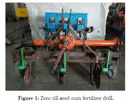
Figure 1: Zero till seed cum fertilizer drill.
Major components are:
1. Frame
2. Seed and fertilizer box
3. Seed metering device
4. Furrow openers and boot
5. Power transmission unit
6. Disc type rotatory coulters
7. Ground drive wheel
8. Seed and fertilizer delivery tubes
Frame
Zero drill chassis must be sturdy and durable as all parts are mounted on it with dimensions of 120 × 45 cm. It is made of mild steel corner iron (5 × 5 × 1 cm) that is welded together to give the desired strength and rigidity. Furrow openers, drive wheel, hoist bracket and tank were attached to the frame. The frame of the three teeth drill has a length of about 120 cm. The holes are 1.5 cm in diameter and 40 cm apart from each other. The machine can be easily set up with any 35 HP tractor. The height of the machine ranges from 70 to 100 cm.
Design of frame
Frame was designed subjected to torsion and bending due to induced draft. Design was based on the stresses produced in the frame.
Seed and fertilizer box
It is a box-shaped structure made of mild steel or galvanized iron and equipped with a lid. On some models, the bottom of the box has a small mixer that shakes the seeds while the drill is running and prevents the seed from clogging. The seed dosing mechanism is packed. This machine used a well-made seed and fertilizer box. There is a rectangular box with separate compartments for seeds and fertilizer.
The top of the box was 600 x 220 mm and the bottom was 120 mm. Its shape was trapezoidal with a height of 200 mm. The box was made up of M.S. 18 gauge sheet and plastic plate. The total size of the box was 600 x 220 x 200 mm. The upper part of the box is rectangular. The depth of the box was kept at 200 mm. Rectangular boxes, one for seed (15 kg capacity) and the other for fertilizer (15 kg), made of 18-gauge light steel sheet and plastic plate, were mounted on a frame with support (Figure 2).
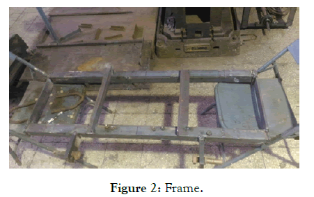
Figure 2: Frame.
Design of seed box
The seed box made of MS sheet. The design of the seed box was done by following procedures [5].
Seed metering mechanism
The mechanism for collecting seeds from the seed box and transporting them to the seed tube is called the seed measuring mechanism. The tilting plate measuring mechanism is adopted to deliver the seeds through the seed tube. Metering plate with 8 holes according to the size of the maize seeds (Figure 3).
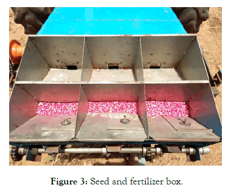
Figure 3: Seed and fertilizer box.
Fluted feed type
The ribbed wheel, also known as the split roller, is guided by a square axis. There is a horizontal stroke along the outer periphery of the wheel and the wheel can be moved sideways depending on the sowing speed. These rollers are mounted at the bottom of the seed box. They receive seeds in longitudinal thickets and enter the seed tube through the seed hole.It is a seed metering device with an adjustable ribbed roller for collecting and transferring the seed into the seed tube. The corrugated feed type mechanism consists of a corrugated wheel, a feed roller, a feed cut and an adjustable gate for different grain sizes.
For feeding of various sizes and shapes, a dosing roller dosing device was used. When enabled, a continuous flow of seed is provided at any working speed. The seed metering mechanism consisted of a standard aluminum sliced seed metering unit. The seed metering rollers were fixed or fixed on a square mild steel bar measuring 20 x 20 mm and 400 mm long. Spindle fixed inside the rollers and through which the roller rotates. By rotating the roller in the seed-filled envelope, the seed flows out of the roller housing in a continuous flow. Turning on the slotted rollers, they squeeze the seed onto the edge of the seed pan attached to the bottom of the seed metering box, which guides the seed through the plastic seed tubes to the opening in the groove (Figure 4).
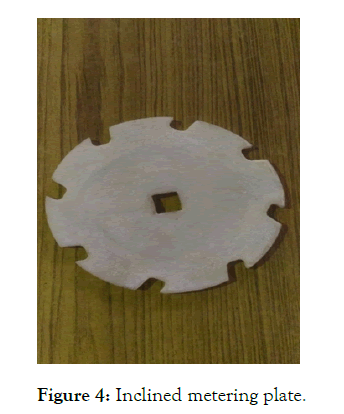
Figure 4: Inclined metering plate.
Design of seed metering mechanism
The design of the seed measuring mechanism was based on the gear in which the flutes or pockets were formed in a circle. It is designed for seed collection and delivery while the machine is moving. The seed mechanism was designed to transport a maximum of two seeds. The number of flutes varied with the distance needed between individual seeds or seed lots. A seed metering disc was designed and manufactured because the flute size varies with the size and shape of the seed. The seeds were selected to determine whether the developed seed measuring mechanism would work on oval, spherical and flat seeds.
The seed box consisted of a seed metering disc, spacers, side plates, frame and feed tube. The measuring disc was made of plastic and gaskets, the side plates made of acrylic material. Inclined metering discs with a diameter of 15 cm and a thickness of 5 mm were selected. A grooved roller mechanism with 6 groove fertilizer movement was selected.
Furrow openers
Furrow openers are those parts of the furrow which open the furrows in the ground for seed placement. When the furrow openers open the soil, seeds and fertilizers enter the furrow through the open seed and fertilizer feed pipes and through the boots the seed and fertilizer enter the soil. There were different types of furrow openers. This zero seed drill and fertilizer drill have 3 chisel openers. They can be deployed in different cultures as needed. The cutting opening (operating point) of the groove openers was made with a 2 mm thick carbon tip welded on a lightweight steel plate with an angle of inclination of 20 ° to create a narrow crack without much disturbance on the ground.
The developed machine does not have a separate drive wheel for transferring energy to the measuring mechanism. Power was transmitted to the ground via the wheel. These groove openers, fixed to the tooth, open a narrow gap of 2-5 cm. The front of the groove openers has a piece of carbon steel welded across the nose, tip and sides to reduce wear. The furrow opener is welded with a flat, lightweight steel shaft. The quality of the material used to make the slot openers will ultimately determine the quality and duration of the drill. The double boot is designed behind the furrow opening to receive a tube (steel tape or polyethylene tube with a minimum diameter of 25 mm) from the seed and fertilizer metering units [8].
Design of furrow opener
The draft force on the furrow opener is assumed to be 15 kgf/drop and operates at a height of h/3 from the bottom of the furrow opener, where h is the total length of the furrow opener and spindle. The groove opener has a maximum height of 40 cm and a height adjustable up to 120 mm.
The design procedures followed which was given by Sharma.
Power transmission unit
The power transmission unit consisted of the following components:
1. Turn to ground.
2. Power transmission shaft.
3. Location of chain and sprockets.
Wheel on the ground
An earth wheel was provided on the front of the chassis, which was a functional part of the power transmission unit. The rotation of the wheel on the ground caused the vertical rotor to rotate through the position of the chain and sprocket. A simple bicycle wheel was used as the ground wheel. The actual wheel diameter on the ground was 600 mm. The wheel turned to the ground with the shaft on which it was mounted (Figure 5).
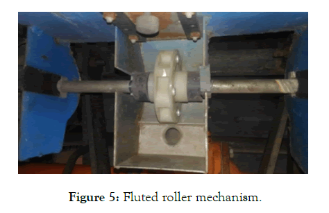
Figure 5: Fluted roller mechanism.
Transmission
The gearbox used on the chassis had a bevel gear set with 11 gears on the gear and 18 gears on the gear; the material used for the transfers was the cost of iron. This provides reduction of the gear unit from 540 rpm to 330 rpm. The gearbox is lubricated in an oil bath. The spindle on which the gear is mounted is split while the gear is welded to the main drive shaft (Figure 6).
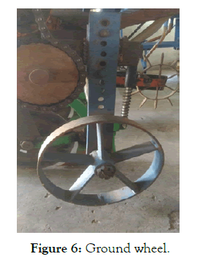
Figure 6: Ground wheel.
Power transmission shaft
The power transmission shaft was supported by two pedestal bearings mounted on the main frame. The tree consisted of a 40 mm diameter and 120 cm long M.S light strip. It turned inside the pedestal bearings, which were secured at the ends, by turning the tapered gears in the gearbox. The tractor's PTO shaft transmits 540 rpm to the gearbox with 11 and 18 teeth. A gear with three different number of teeth (26, 28 and 30) was mounted on this axis to transfer energy from the gearbox to the rotor shaft. With the placement of the chain and sprocket, the power delivered to the shaft by the gearbox was transferred to the coulter rotation (Figure 7).
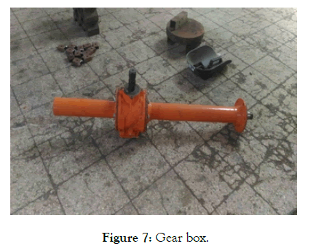
Figure 7: Gear box.
Design of power transmission
The coulters will only cut residues if they penetrate the ground with shallow depth and rotate. This will only happen if there is sufficient vertical pressure and adequate soil resistance to the coulter's bleeding force. An energy source was provided to rotate the coulters with a special rotation of three different speeds using the 26, 28, 30 gear sprockets available from the CRIDA workshop (Figure 8).
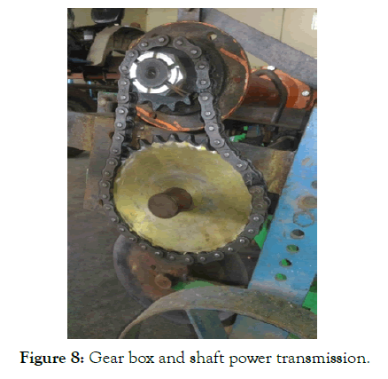
Figure 8: Gear box and shaft power transmission.
The gearbox develops 330 rpm. It was transmitted to the coulters using different gears. At the end of the gearbox is a 14-tooth gear which was constant. The developed speed was distributed to the coulters using 14 sprocket sprockets mounted on a shaft mounted on a pedestal bearing frame and a blanket with a speed ratio of 1:1.
Coulters
From all different types of box openers, experience and experiments have shown that disc coulters have the best residue management. With a sharp edge, they cut the soil and debris and open the furrow. This causes less disturbance of the soil, which is one of the objectives of zero-level agriculture; since less soil disturbance means less moisture and less nutrient loss. Therefore, the disc coulter is selected for further research and is used to design the drill. The disc coulters have various parameters that affect their performance and their interaction with the ground. Disc diameter, disk thickness, edge angle, disk angle, inclination angle, and even depth of cut are parameters that can change the forces exerted on the disk by rotating the ground. Edge angle is the slope of the disk edge that determines its sharpness.
A coulter with a diameter of 30 cm and a thickness of 2 mm was chosen for cutting residues (Figure 9).
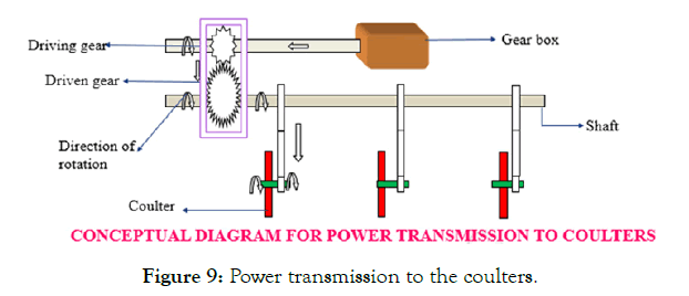
Figure 9: Power transmission to the coulters.
Design of coulters
The 30 cm diameter and 2.5 mm thickness of the rotary disc coulter has been selected as an essential tool for carrying out the recommended post-harvest application of seeds and fertilizers. The main function of this tool is to reduce crop residues on the soil surface.
The edges are sharpened to effectively cut residues. A conventional coulter is selected to reduce soil disturbance affecting the moisture content.
Ground drive wheel
The drive transmission mechanism consists of a ground drive wheel, sprocket-chain assembly and a driven shaft that carry the seed picking discs. When the seed drill moves in the field, the drive wheel rotates due to its contact with soil and the sprocket wheel also rotes. The chain connecting the drive wheel sprocket and driven wheel sprocket rotates the shaft carrying the seed metering discs.
The ground wheel was made up of 30 x 5 mm MS flat having length 250 cm by bending in circular shape and 12 pentagonal pegs (80 mm) were welded at the periphery of the wheel for better griping with soil which controls the seed metering mechanism of the drill (Figure 10).
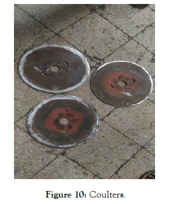
Figure 10: Coulters.
Seed and fertilizer delivery tubes
Seeding tubes were made of a transparent plastic tube according to the distance between the different rollers and the opening tubes of the furrow opener. Each seed tube was attached to the seed distributor at one end and the other end was attached to the trunk opening at the furrow. The time of fall of the seed through the tube is affected by the size and type of tube, as well as by the impact of the seed and the rebound against the wall of the tube. Transparent plastic tubes with a diameter of 25 mm and a thickness of 2 mm were selected (Figures 11 & 12).
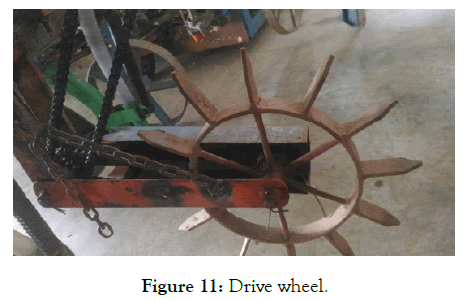
Figure 11: Drive wheel.
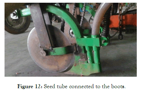
Figure 12: Seed tube connected to the boots.
Results and Discussions
The developed and manufactured seed drill with direct seed fertilizer had to undergo tests to evaluate the performance of the machine developed under various field conditions.
Conclusion
The main purpose of this document is to gain a proper understanding of the various aspects or limitations of self-propelled drills for rotary sowing and the various weeding methods to reduce farmer’s money, labor, time, physical efforts for economic cultivation. A sincere effort must be made to develop appropriate seeding/ planting equipment or method to ensure greater profitability and stability in economic terms. Adjustable blades, rotary coulters can definitely affect the drill's performance with seed fertilizer. The design considerations of the machine also have a greater impact on the operation of the drill with a rotary fertilizer with zero seeder.
REFERENCES
- Thakur TC, Kumar A. Machinery for Zero-Till Surface Managed Crop Residue Systems. Progress and Prospects Conservation Agriculture. Status and Prospects, Centre for Advancement of Sustainable Agriculture. 2005.
- Hobbs PR, Mehla RS. The problem of late planting wheat. Addressing resource conservation Issues in Rice-Wheat Systems of South Asia. A resource book. Rice Wheat Consortium for Indo-Gangetic Plains-International Maize and wheat Improvement Centre. 2003.
- Ashok Y, Malik RK, Bansal NK, Gupta RK, Samar S, Hobbs PR. National agricultural technology project Indian council of agricultural research rice-wheat consortium for the Indo-Gangetic. Plains CG Block, National Agriculture Science Centre (NASC). 2002.
- Ghosal MK, Pradhan SC. Performance study of a low cost manually Operated cup feed metering seed drill for sowing green gram at Bhubaneswar. Int J Agriculture Engineering. 2013;5(1):6-11.
- Sahoo PK , Srivastava AP. Seed pattern characteristics of different metering systems for soaked okra seed. J Agricultural Eng. 2008;45(1):1-6.
- Dhaliwal IS, Sukla LN. Tractor drawn seed-cum-fertilizer drill for oil seeds. Farm Equipment for Panjab Agriculture. 2002;5:49-51.
- Mukesh D, Sharma AP. Zero-tillage in wheat crop under heavy soils. Agric Mech in Asia, Africa and Latin America. 2010;17:15-16.
- Unadi A, Khurmi K, Gupta CP. Development of two wheel tractor operated seed cum fertilizer drill. Agril. Mechanization in Asia, Africa and Latin America. 1995;25(1):25- 28.
Citation: Ramya K, Lokesh M, Ravi Chandra Charyulu K (2020) Design and Development of Zero till Rotary Cum Fertilizer Drill Coulter type Seed. Agrotechnology 9: 199. doi: 10.35248/2168-9881.20.9.199.
Copyright: © 2020 Ramya K, et al. This is an open-access article distributed under the terms of the Creative Commons Attribution License, which permits unrestricted use, distribution, and reproduction in any medium, provided the original author and source are credited.
