Indexed In
- Open J Gate
- Genamics JournalSeek
- JournalTOCs
- China National Knowledge Infrastructure (CNKI)
- Electronic Journals Library
- RefSeek
- Hamdard University
- EBSCO A-Z
- OCLC- WorldCat
- SWB online catalog
- Virtual Library of Biology (vifabio)
- Publons
- MIAR
- Euro Pub
- Google Scholar
Useful Links
Share This Page
Journal Flyer

Open Access Journals
- Agri and Aquaculture
- Biochemistry
- Bioinformatics & Systems Biology
- Business & Management
- Chemistry
- Clinical Sciences
- Engineering
- Food & Nutrition
- General Science
- Genetics & Molecular Biology
- Immunology & Microbiology
- Medical Sciences
- Neuroscience & Psychology
- Nursing & Health Care
- Pharmaceutical Sciences
Research Article - (2023) Volume 14, Issue 4
Comparison of the Effectiveness of Sawdust and Sponge Gourd (Luffa cylindrica) in Loss Circulation and Filtration Control
Stephen Gekwu Udeagbara1*, Ndubuisi Uchechukwu Okereke2, Ifeanyi Alex Oguamah2, Anthony Kerunwa2, Joshua Oluwadare Oyebode3 and Dipo-Salami Temisan12Department of Petroleum Engineering, Federal University of Technology, Owerri, Nigeria
3Department of Civil Engineering, Afe Babalola University, Ado-Ekiti, Nigeria
Received: 19-Jul-2023, Manuscript No. JPEB-23-22298; Editor assigned: 21-Jul-2023, Pre QC No. JPEB-23-22298 (PQ); Reviewed: 07-Aug-2023, QC No. JPEB-23-22298; Revised: 14-Aug-2023, Manuscript No. JPEB-23-22298 (R); Published: 21-Aug-2023, DOI: 10.35248/2157-7463.23.14.536
Abstract
Drilling fluid is a suspension of clay in water and some other additives to improve the quality. It is used in oil and gas drilling operations to carry rock cuttings to the surface and also to lubricate and cool the drill bit. It possesses unique characteristics to fulfill the functions during the course of drilling.
Loss circulation is a drilling problem where the drilling fluid is partially or completely lost into a highly permeable formation whereas filtration is the loss of drilling fluid into a permeable formation which has led to many problems in drilling operations. This research work was tailored towards use of agricultural wastes (sawdust and sponge gourd (Luffa cylindrica)) in lost circulation and filtration control. The wastes were properly processed, used to prepare standard drilling fluids that met API standard and the properties were analyzed and characterized.
The properties investigated in this research work were filtration, density, specific gravity, pH and the rheological properties. For the sawdust (150 microns and 300 microns), the filtration, density, specific gravity, pH, plastic viscosity, apparent viscosity, yield point, 10-s gel strength and 10-mins gel strength value fall within the range of 10.6 ml-21.4 ml, 8.7 ppg-9.0 ppg, 1.04-1.08, 7.00-8.45, 6 cp-11 cp, 12 cp-33 cp, 8 lb-46 lb/100 ft2, 9 lb-55 lb/100 ft2 and 18 lb-65 lb/100 ft2 respectively. While for Luffa cylindrica, the values were 14 ml, 2 ml-36 ml, 8.6 ppg-8.9 ppg, 1.03- 1.06, 7.11-7.92, 5 cp-11 cp, 13 cp-37.5 cp, 7 lb-61 lb/100 ft2, 10 lb-62 lb/100 ft2 and 20 lb-75 lb/100 ft2 respectively.
It was observed from the results that Luffa cylindrica could not give an encouraging result, rather, sawdust of particle size 300 microns, with a concentration of 16 g/350 ml is the best drilling fluid additive to mitigate loss circulation and filtration in drilling operations. Sawdust with the right particle size should be encouraged for loss circulation and filtration control in drilling operations
Keywords
Lost circulation; Filtration; Adsorbents; Drilling fluid
Introduction
Background of the study
Drilling is a cutting process that uses a drill bit to cut a hole of a circular cross-section in solid materials. Drilling fluids are used during this process to perform a number of functions. Drilling mud, also called drilling fluid, in petroleum engineering, is a heavy, viscous fluid mixture that is used in oil and gas drilling operations to carry rock cuttings to the surface and also to lubricate and cool the drill bit. The drilling mud, by hydrostatic pressure, also helps prevent the collapse of unstable strata into the borehole and the intrusion of water from water-bearing strata that may be encountered [1].
Drilling fluids are traditionally based on water, either fresh water, seawater, naturally occurring brines, or prepared brines. Many muds are oil-based, using direct products of petroleum refining such as diesel oil or mineral oil as the fluid matrix.
A typical water-based drilling mud contains clay, usually bentonite, to give it enough viscosity to carry cutting chips to the surface, as well as a mineral such as barite (barium sulphate) to increase the weight of the column enough to stabilize the borehole. Smaller quantities of hundreds of other ingredients might be added, such as caustic soda (sodium hydroxide) to increase alkalinity and decrease corrosion, salts such as potassium chloride to reduce infiltration of water from the drilling fluid into the rock formation, and various petroleum-derived drilling lubricants. Oil and synthetic based muds contain water (usually brine), bentonite and barite for viscosity and weight, and various emulsifiers and detergents for lubricity [2].
Composition of drilling fluids: Water-based drilling mud most commonly consists of bentonite clay (gel) with additives such as barium sulphate (barite), calcium carbonate (chalk) or hematite. Various thickeners are used to influence the viscosity of the fluid, e.g. xanthan gum, guar gum, glycol, carboxymethylcellulose, Polyanionic Cellulose (PAC), or starch.
In turn, deflocculants are used to reduce viscosity of clay-based muds; anionic polyelectrolytes (e.g. acrylates, polyphosphates, Lignosulfonates (Lig) or tannic acid derivates such as Quebracho) are frequently used. Red mud was the name for a Quebracho-based mixture, named after the colour of the red tannic acid salts; it was commonly used in the 1940s to 1950s, and then was made obsolete when lignosulfonates became available. Other components are added to provide various specific functional characteristics as listed above. Some other common additives include lubricants, shale inhibitors, and fluid loss additives (to control loss of drilling fluids into permeable formations). A weighting agent such as barite is added to increase the overall density of the drilling fluid so that sufficient bottom hole pressure can be maintained thereby preventing an unwanted (and often dangerous) influx of formation fluids [3].
Loss circulation: Loss circulation is a drilling problem where the drilling fluid is partially or completely lost in to the formation. During Loss circulation, Pit volume and mud flow out will decrease. Ideally while we are drilling, there should be very less decrease in drilling fluid volume which is required to fill the extra hole drilled. But in practice, more volume of drilling fluid is lost while drilling, which is lost into the formation.
One of the problems in rotary drilling is loss circulation. In order to transport cuttings and cool the bit, drilling fluids are supposed to be circulated down to the bottom hole and come back to the surface. Loss circulation or lost returns may be defined as the loss to formation voids of the drilling fluids or cement slurries used in the process of rotary drilling and well completion. The loss may vary from a gradual lowering of mud level in the pits to a complete loss of returns. Not to be confused with lost circulation is the continuous reduction in mud volume caused by the loss of the fluid phase of mud as filtrate and the solid phase as filter cake during the continuous filtration process which occurs on permeable formation surfaces. When loss circulation occurs, drilling fluids are lost. In partial loss circulation, mud continues to flow to surface with some loss to the formation. Total loss circulation, however, occurs when all the mud flows into a formation with no return to surface. If drilling continues during total loss circulation, it is referred to as blind drilling [4]. This is not a common practice in the field, unless all of the following criteria are met:
• The formation above the thief zone is mechanically stable.
• There is no production.
• The fluid is clear water.
In overbalance condition, hydro-static pressure of drilling mud is greater than formation pressure which pushes the liquid part of drilling fluid into the formation while the solids are deposited on the borehole wall and forms the filter cake which prevents further losses. The liquid part which is lost to the formation is called filtrate and the losses while the filter cake is depositing across the borehole wall is termed as ‘spurt loss’.
Loss circulation can be due to number of reasons:
• Due to the presence of fault.
• Mud weight or Equivalent Circulating Density (ECD) higher than formation fracture gradient, induces fractures into the formation.
• Presence of Permeable Formation, etc.
To stop further fluid loss, Loss Circulation Materials (LCMs) have to be added to the mud. This kind of incidents may have a heavy financial and environmental burden, which justifies the high price of LCM products. It would also increase the high cost of nonproductive rig time that is very valuable [4]. Above all, loss circulation can lead to mud levels falling, which can cause an underbalanced pressure state of the well. In severe cases, it may lead to a kick or even a blowout [5].
Instances of loss circulation usually occur in cavernous, karst, highly permeable and naturally fractured formations [6]. If loss- circulation zones are anticipated, preventive measures should be taken by treating the mud with Loss of Circulation Materials (LCMs) and preventive tests such as the formation integrity test should be performed to better define the mud weight window to limit the possibility of loss of circulation. Hence, loss circulation is a very important issue which has led to a lot of research dedicated to minimize its negative impacts and the biggest breakthrough has been LCMs. They are designed to seal fractures and minimize mud loss [4].
Loss circulation control: During drilling or cementing loss circulation may be encountered due to the presence of highly permeable formations, e.g. high natural permeability in sandstone, or large natural fractures and vugs as found in limestones. Basically, loss circulation treatments can be divided into two categories: Those where the loss circulation is solved by the addition of solid materials to the drilling mud; and those where the problem can only be solved by the use of a non-mud system. Normally when loss circulation occurs, the first attempt to cure the problem is always by a reduction in mud weight and/or the addition of granular, fibrous, or lamellate material to the mud. The decision to use what material has been shown to be dependent on the type of lost circulation zone and the severity of the losses, but in many cases a number of different materials are used, sometimes with, sometimes without, success. Generally, while drilling we face loss circulation, if Losses are minor they can be neglected but major losses requires treatment because the cost of drilling fluid is very high [2].
The complete prevention of loss circulation is impossible, because some formations, such as inherently fractured, cavernous, or high- permeability zones, are not avoidable if the target zone is to be reached. However, limiting circulation loss is possible if certain precautions are taken especially those related induced fractures. These precautions are:
• Adequate hole cleaning.
• Avoiding restrictions in the annular space.
• Setting casing to protect upper weaker formations within a transition zone.
• Updating formation pore pressure and fracture gradients for better accuracy with log and drilling data.
Filtration: As oil wells are drilled by the rotary method, drilling mud circulates up the annulus between drill pipe and well wall.
Drillers adjust mud density so that the pressure at the bottom of the mud column is several hundred psi greater than the pressure of reservoir fluid. As a result of this pressure difference, the liquid part of the mud filters into the rock around the bore and mud solids deposit as a filter cake on the well wall. For many reasons the petroleum industry, has spent much money and energy to determine the volume of mud filtrate that enters rock around the well bore and dedicated much research effort to reduce this volume. Among the reasons for attempts to determine the volume of mud filtrate and to reduce this volume are the following:
• If filtrate damages the permeability of oil sand, the resultant damage to oil well productivity will depend on the distance that the filtrate invades the oil sand; reduction of filtrate volume may, therefore, increase well productivity.
• Filtrate that penetrates shale sections may cause the shale to swell and to slough into the well bore. Uncontrolled sloughing may stick drill pipe. Reduction in filtrate volume may reduce drilling trouble.
• Electric log resistivity curves are changed by invasion of a mud filtrate; the change depends on the depth to which filtrate invades. Knowledge of this depth is necessary before resistivity logs can be interpreted accurately.
For these reasons, specifications that place an upper limit to drilling mud filter loss are now written into almost all drilling programs [7].
Filter cake is the residue deposited on a permeable medium when slurry, such as a drilling fluid, is forced against the medium under a pressure. Filtrate is the liquid that passes through the medium, leaving the cake on the medium. Drilling mud is tested to determine filtration rate and filter-cake properties. Cake properties such as cake thickness, toughness, slickness and permeability are important because the cake that forms on permeable zones in the wellbore can cause stuck pipe and other drilling problems. Reduced oil and gas production can result from reservoir damage when a poor filter cake allows deep filtrate invasion. A certain degree of cake buildup is desirable to isolate formations from drilling fluids. In open hole completions in high-angle or horizontal holes, the formation of an external filter cake is preferable to a cake that forms partly inside the formation. The latter has a higher potential for formation damage [8].
Materials and Methods
The materials and equipment used in this research are sawdust, Luffa cylindrica, bentonite, barite, additives (CMC, PAC), distilled water, laboratory glass wares, filter paper, caliper, set of sieves, grinding machine, oven, weighing balance, filter press, hamilton beach stirrer, pH meter, mud balance, rotational viscometer, etc.
Preparation of LCMs: Sawdust and Luffa cylindrica
Procedure: Sawdust was collected from ABUAD farm, while Luffa cylindrica was bought from a local market in Ado-Ekiti. Both were washed with distilled water thoroughly to remove impurities, sun- dried for three days to remove moisture. Luffa cylindrica was dried further in an oven at 105 ºC for three hours, and sawdust at 45 ºC for thirty minutes to ensure that they are properly dried and remove adsorbed gases and impurities from the surface [9]. The materials were grinded and sieved into 150 microns and 300 microns sizes respectively (Figures 1-4).
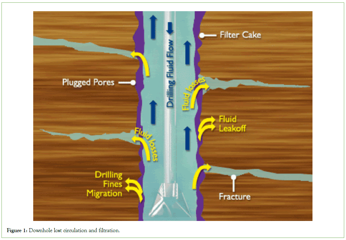
Figure 1: Downhole lost circulation and filtration.
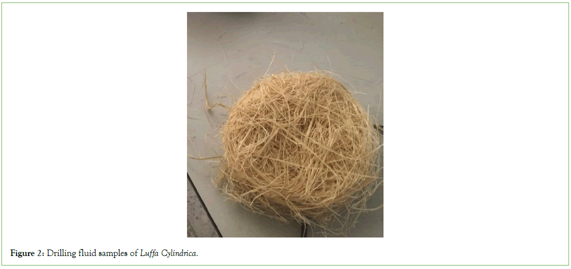
Figure 2: Drilling fluid samples of Luffa Cylindrica.
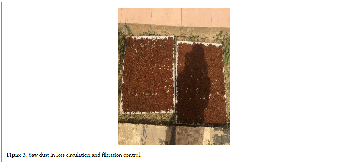
Figure 3: Saw dust in loss circulation and filtration control.
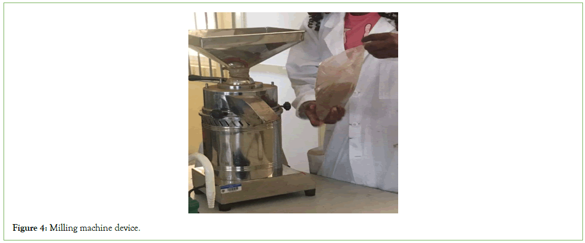
Figure 4: Milling machine device.
Preparation of control drilling fluid
Procedure: A standard drilling fluid used as a control was prepared by adding: 350 ml of water, 2.25 g of bentonite, 0.2 g of CMC, 4 g of PAC, 0.2 g of both KCl and Na2CO3, and 10 g of barite in a beaker and were thoroughly mixed with the Hamilton beach stirrer at 10 minute intervals of adding the materials, until a homogeneous mixture was obtained. The prepared sample was characterized for the necessary properties and poured in a bottle and labeled for further testing [10].
Preparation of drilling fluid with Loss Circulation Materials (LCMs)
Procedure: The samples were prepared by adding the following quantities of materials:
• 350 ml of water.
• 25 g of bentonite.
• 4 g, 8 g, 12 g and 16 g of 150 microns and 300 microns’ sawdust respectively.
• 4 g, 8 g, 12 g and 16 g of 150 microns and 300 microns’ Luffa cylindrica respectively.
• 0.2 g of both KCl and Na2CO3.
• 10 g of barite.
The materials listed above were used to formulate water-based muds containing loss circulation materials of different particle sizes and weights. The materials were thoroughly mixed with the Hamilton beach stirrer at 10 minute intervals of adding the materials, until a homogeneous mixture was formed. The prepared samples were characterized and poured in bottles and labeled for further testing [11]. This procedure was carried out for all particle sizes and weights listed for both sawdust and Luffa cylindrica (Figures 5 and 6).
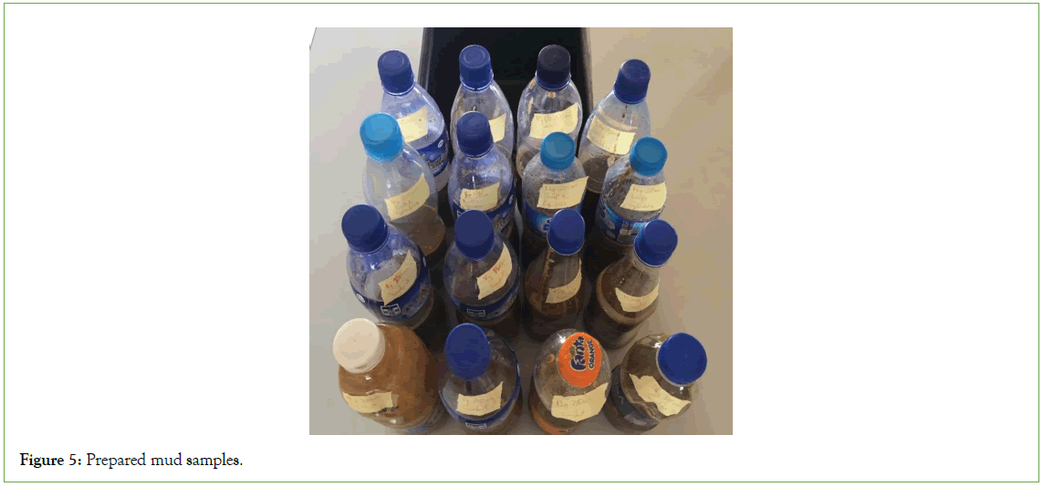
Figure 5: Prepared mud samples.
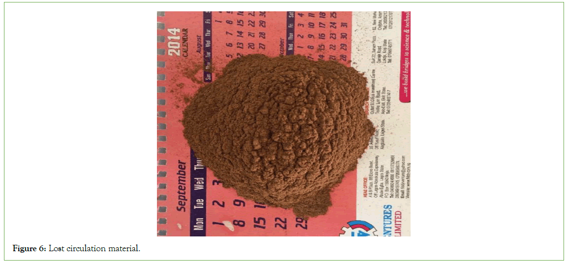
Figure 6: Lost circulation material.
Determination of filter loss of mud
The filter loss of the mud is a measure of the ability of mud to plaster the wall of the borehole with an impermeable filter cake. The lower the permeability of plaster, the thinner is cake and the lower the filtrate volume. This property is dependent on the amount and physical state of colloidal material in the mud. A mud having sufficient colloidal content minimizes the drilling difficulties. The loss of liquid from a mud due to filtration is controlled by the filter cake formed from the solid constituents in the drilling fluid. The test in the laboratory consists of measuring the volume of liquid forced through the mud cake into the formation drilled in a 30-minute period under given pressure and temperature using a standard sized cell [12-15].
It was found in early works that the volume of fluid lost is roughly proportional to the square root of the time for filtration.
The two commonly determined filtration rates are the low-pressure, low temperature a n d high-pressure high-temperature [16-18].
Filtration procedure
• Filter paper was placed on the base of the mud cell. A rubber gasket was placed to avoid leakage between the base cap and the cell.
• The mud was poured into the mud cell and it was fixed onto the base. The T screw was tightened and it was ensured that all valves were closed.
• The pressure valve was turned to 100 psi and the stopwatch started simultaneously.
• The graduated cylinder below the mud cell indicated the water loss through the filtrate.
• The water volume was read at the following intervals from the time pressure was applied: 5 min, 10 min, 15 min, 20 min, 25 min and 30 min.
• After the test was completed, the pressure valve supply was turned off.
• The T screw was unscrewed and the cell with the base removed.
• The mud was poured out and the cell rinsed with water.
• The cell was unscrewed from the base to obtain the filter paper.
• The filter paper contained a layer of mud which is the mud cake.
• The thickness of the mud cake was measured with a Vernier caliper.
• The apparatus was washed thoroughly and dried.
• The procedure was repeated for all drilling mud samples (Figure 7).
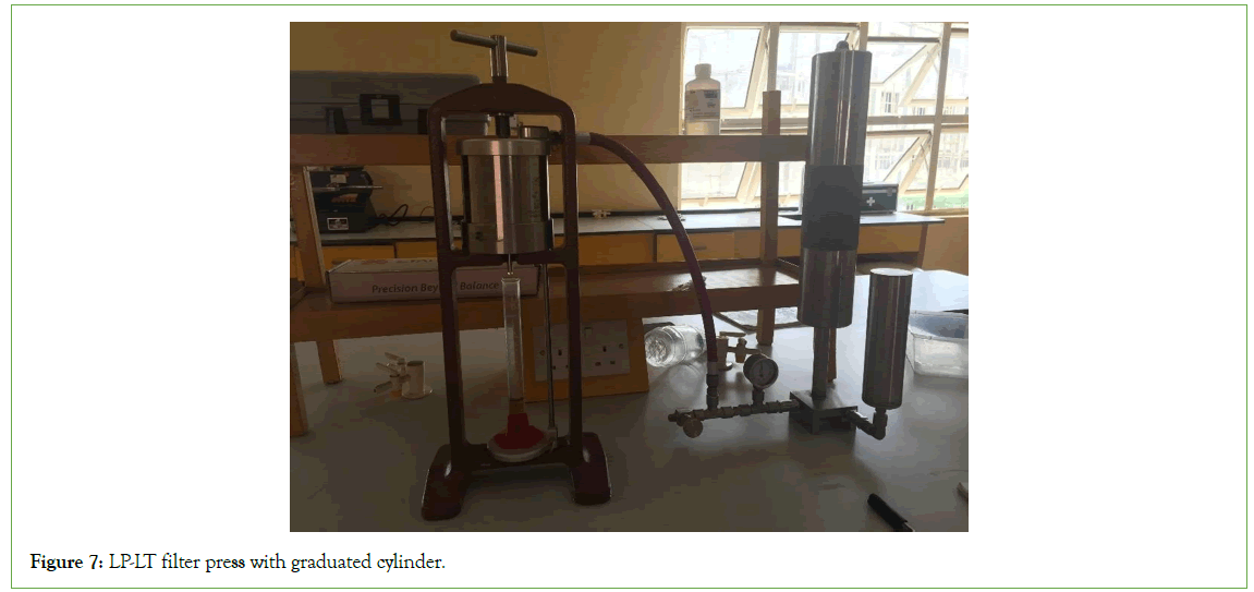
Figure 7: LP-LT filter press with graduated cylinder.
Results and Discussion
The results tabulated on Tables 1-5 summarized the variation of the properties of drilling fluid samples containing varying quantities and sizes of Saw dust and Luffa cylindrica. These properties include density, specific gravity, pH, plastic viscosity, apparent viscosity, yield point and gel strength. Some of these properties were found to increase with increase in mass of loss circulation materials, whereas some were found to decrease with increase in mass of same loss circulation materials.
| Mass (g) | Particle size | 5 mins | 10 mins | 15 mins | 20 mins | 25 mins | 30 mins | Mud cake thickness |
|---|---|---|---|---|---|---|---|---|
| 0 | Control | 4 | 7.2 | 10 | 12.4 | 14 | 15.4 | 1.2 |
| 4 | 300 micron Sawdust | 3.8 | 6.8 | 9.2 | 11.6 | 13.4 | 15 | 3.4 |
| 8 | 300 micron Sawdust | 4.4 | 7.4 | 9.2 | 12.2 | 14 | 15.6 | 2.8 |
| 12 | 300 micron Sawdust | 3 | 5 | 7.2 | 9.2 | 11 | 12.2 | 3.7 |
| 16 | 300 micron Sawdust | 2.6 | 4.2 | 6.2 | 7.8 | 9.4 | 10.8 | 4 |
| 4 | 300 micron Luffa | 6.2 | 8.8 | 10.4 | 12 | 13.2 | 14.4 | 3.2 |
| 8 | 300 micron Luffa | 6.2 | 8.6 | 10.4 | 12 | 13.2 | 14.2 | 3.6 |
| 12 | 300 micron Luffa | 7 | 11.4 | 14.6 | 17.4 | 19.6 | 21.6 | 4.1 |
| 16 | 300 micron Luffa | 8.6 | 12 | 14.6 | 16.6 | 18.6 | 20.2 | 4.8 |
| 4 | 150 micron Sawdust | 5 | 8.2 | 10.2 | 12 | 13.4 | 14.2 | 4.8 |
| 8 | 150 micron Sawdust | 8.2 | 12.2 | 15 | 17.4 | 19.6 | 21.4 | 4.7 |
| 12 | 150 micron Sawdust | 4 | 6 | 7.6 | 8.8 | 9.8 | 10.6 | 5.3 |
| 16 | 150 micron Sawdust | 5.8 | 8.2 | 10 | 11.4 | 12.6 | 13.6 | 5.4 |
| 4 | 150 micron Luffa | 4.9 | 7.3 | 8.9 | 10.3 | 11.3 | 12.3 | 3.3 |
| 8 | 150 micron Luffa | 10 | 14.2 | 18 | 20.8 | 23.4 | 25 | 5.2 |
| 12 | 150 micron Luffa | 9.2 | 15 | 20 | 24.6 | 28 | 31.4 | 3.7 |
| 16 | 150 micron Luffa | 16.4 | 23 | 28 | 31 | 33.2 | 36 | 4.5 |
Table 1: Filtrate volume at five minute intervals and mud cake thickness of mud samples.
| Properties | Control | 4 g | 8 g | 12 g | 16 g |
|---|---|---|---|---|---|
| Density(ppg) | 8.45 | 8.7 | 8.6 | 8.7 | 8.9 |
| Specific gravity | 1.01 | 1.04 | 1.03 | 1.04 | 1.06 |
| pH | 9.16 | 7.11 | 7.5 | 7.71 | 7.16 |
| Plastic viscosity (cp) | 9 | 5 | 9 | 10 | 8 |
| Yield point (lb/100 ft2) | 8 | 20 | 12 | 25 | 52 |
| Apparent viscosity (cp) | 13 | 15 | 15 | 22.5 | 34 |
| Gel strength (10 Seconds) (lb/100 ft2) | 12 | 15 | 25 | 35 | 54 |
| Gel strength (10 Minutes) (lb/100 ft2) | 20 | 25 | 35 | 40 | 64 |
Table 2: Results of properties for control and 300 micron luffa cylindrica.
| Properties | 4 g | 8 g | 12 g | 16 g |
|---|---|---|---|---|
| Density (ppg) | 8.8 | 8.9 | 8.8 | 8.8 |
| Specific gravity | 1.05 | 1.06 | 1.05 | 1.05 |
| pH | 7.7 | 7.92 | 7.71 | 7.11 |
| Plastic viscosity (cp) | 11 | 7 | 8 | 10 |
| Yield point (lb/100 ft2) | 7 | 61 | 53 | 45 |
| Apparent viscosity (cp) | 14.5 | 37.5 | 34.5 | 32.5 |
| Gel strength (10 seconds) (lb/100 ft2) | 10 | 62 | 53 | 45 |
| Gel strength (10 minutes) (lb/100 ft2) | 25 | 75 | 64 | 55 |
Table 3: Results of properties for 150 micron Luffa cylindrica.
| Properties | 4 g | 8 g | 12 g | 16 g |
|---|---|---|---|---|
| Density (ppg) | 8.75 | 8.85 | 8.8 | 8.9 |
| Specific gravity | 1.05 | 1.06 | 1.05 | 1.07 |
| pH | 8.4 | 8.2 | 8.05 | 8.45 |
| Plastic viscosity (cp) | 8 | 6 | 8 | 10 |
| Yield point(lb/100 ft2) | 8 | 17 | 19 | 24 |
| Apparent viscosity (cp) | 12 | 15.5 | 17.5 | 22 |
| Gel strength (10 seconds) (lb/100 ft2) | 12 | 26 | 25 | 32 |
| Gel strength (10 minutes) (lb/100 ft2) | 21 | 30 | 35 | 42 |
Table 4: Results of properties for 300 micron Sawdust.
| Properties | 4g | 8g | 12g | 16g |
|---|---|---|---|---|
| Density(ppg) | 8.7 | 8.8 | 8.9 | 9 |
| Specific gravity | 1.04 | 1.05 | 1.07 | 1.08 |
| pH | 7.1 | 7 | 7.4 | 7.11 |
| Plastic viscosity(cp) | 10 | 11 | 10 | 11 |
| Yield point(lb/100 ft2) | 8 | 27 | 46 | 37 |
| Apparent viscosity(cp) | 14 | 24.5 | 33 | 29.5 |
| Gel strength (10 seconds) (lb/100ft2) | 9 | 25 | 55 | 45 |
| Gel strength (10 minutes) (lb/100ft2) | 18 | 40 | 65 | 55 |
Table 5: Results of properties for 150 micron Sawdust
For Luffa cylindrica, the particle size and mass do not really affect the density, specific gravity and the pH as they remain averagely the same. The increments in the apparent and plastic viscosities were not uniform. The gel strength was found to increase with increase in mass of the loss circulation material (Luffa cylindrica)
For saw dust, similar results were obtained for density, specific gravity and pH. The increments in apparent and plastic viscosities were not uniform as found with Luffa cylindrica. The gel strength was also found to increase with increase in mass of the loss circulation material (saw dust).
The effect of loss circulation and filtration in drilling operation can be very disastrous as it could lead to a blowout, loss of equipment, personnel and a great damage to the surrounding environment. This can occur if the amount of fluid in the wellbore drops due to lost circulation, fluid column hydrostatic pressure is reduced, which allows gas or fluid under higher pressure to flow into the wellbore.
Another consequence of loss circulation and filtration in drilling operation is dry drilling. Dry drilling occurs when fluid is completely lost from the well bore without actual drilling coming to a stop. The effects of dry drilling ranges from as minor as destroying a bit to as serious as major damage to the wellbore requiring a new well to be drilled. Dry drilling can also cause severe damage to the drill string, including snapping the pipe, and the drilling rig itself.
Figure 8 and Table 1 show the filtration volumes for all mud samples for sawdust and Luffa cylindrica over five-minute intervals, up to thirty minutes. It can be observed generally, that the filtrate volume slows over time.
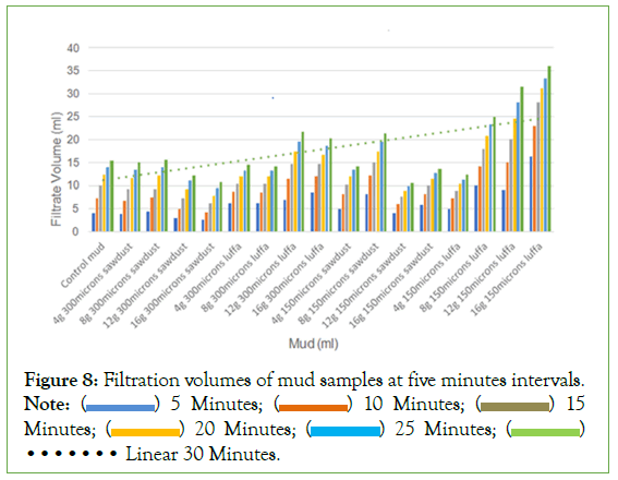
Figure 8: Filtration volumes of mud samples at five minutes intervals. Note: ( ) 5 Minutes; (
 ) 10 Minutes; (
 ) 15
Minutes; (
 ) 20 Minutes; (
 ) 25 Minutes; (
 )••••••• Linear 30 Minutes.
From the tables and the plot, it could be seen that increasing the concentration of 300 micron Luffa cylindrica from 4 g to 16 g produced a better result compared with 150 micron of the same Luffa cylindrica. It could be seen that 16 g of 300 micron Luffa cylindrica produced 20.2 ml of filtrate after thirty minutes whereas the same 16 g of Luffa cylindrica of 150 microns produced 36 ml after same time interval. At the same time, 150 micron and 300 micron particle sizes of saw dust produced 13.6 ml and 10.8 ml respectively. But preferably 300 micron is better.
From these results too, it can be seen that 12 g, 150 microns sawdust sample has the least volume of filtrate. In the first five minutes, 4 ml is produced, after ten minutes the filtrate volume increased by 2 ml, after fifteen minutes, the filtrate increased by 1.6 ml; after twenty minutes, it increased by 1.2 ml, after twenty-five minutes, it increased by 1.0 ml and finally at thirty minutes, the filtrate increased by 0.8 ml. This brings the total volume of the filtrate to 10.6 ml. This progressive decrease in filtrate volume every five minutes indicates that filter cake is being formed on the face of the filter paper, which represents the subsurface formation. The faster it forms, the quicker fluid loss into the formation will be stopped.
It can also be seen from the chart that 16 g, 300 microns’ sawdust also has a low total filtrate volume. In the first five minutes, 2.6 ml is produced, after ten minutes the filtrate volume increased by 1.6 ml, after fifteen minutes, the filtrate increased by 2 ml; after twenty minutes, it increased by 1.6 ml, after twenty-five minutes, it increased by 1.6 ml and finally at thirty minutes, the filtrate increased by 1.4 ml. This brings the total volume of the filtrate to 10.8 ml.
Therefore, the best particle sizes of 150 and 300 microns of sawdust at a concentration of 12 g/350 ml and 16 g/350 ml of water in mud would be good for lost circulation and filtration control in drilling operations. Any of the chosen particle size would definitely arrest the situation at the concentration stated but preferable 16 g/350 ml concentration of 300 micron sawdust is highly recommended based on the control as seen on the tables.
This recommendation is as a result of the sample density and specific gravity been suitable for drilling operations. This density value allows the mud to prevent influx of formation fluid into the wellbore and helps to stabilize the downhole formation condition. The mud has a pH value of 8.45, which indicates that it is alkaline and so will not cause corrosion problems for surface and downhole equipment. This same sample has a plastic viscosity which is not too high to cause drilling problems, but not too low to reduce friction during drilling. Also, the gel strength, 32 for 10 s and 42 for 10 min fall with the acceptable range for drilling operation. 12 g/350 ml concentration of 150 micron size of sawdust though produced a good result but lacks some of the qualities outlines above [19,20].
Generally speaking, for commercial purposes like in preparation of drilling fluid for drilling operation to mitigate lost circulation and filtration loss, sawdust of right particle size is preferred to sponge gourd (Luffa cylindrica).
Figure 9 shows a graph of mud cake thickness for all the mud samples. It is important that sufficient mud cake be formed to properly seal permeable formations. However, it is also important that the mud cake not be too thick. Excessive mud cake thickness can lead to various problems such as:
1.Increased surge and swabbing due to reduced annular clearance.
2. Tight spots in the hole that cause excessive drag.
3. Differential sticking of the drill string due to increased contact area and rapid development of sticking forces caused by higher filtration rate.
4. Primary cementing difficulties due to inadequate displacement of filter cake.
5. Increased difficulty in running casing.
It can be observed that the mud cake thickness for the sample with the least filtration volume is 5.3 mm, while the sample with the next least filtration volume (the recommended) has a mud cake thickness of 4.0 mm. The mud cake thicknesses of the two samples with the least filtrate volumes are generally good and fall within expected range (Tables 1-5) (Figures 8 and 9).
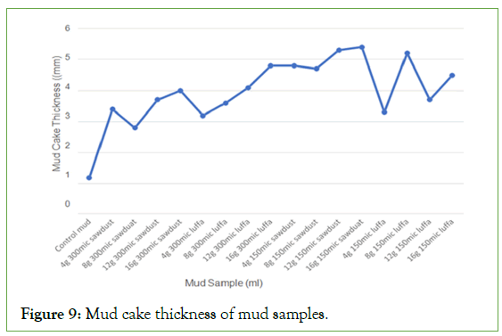
Figure 9: Mud cake thickness of mud samples.
Conclusion
Based on the experiments carried out on two particle sizes of sawdust and Luffa cylindrica, the following conclusions could be drawn:
Sawdust is more effective in reducing filtration and loss circulation of drilling fluid compared with Luffa cylindrica. 150 microns (12 g/350 ml concentration of sawdust in mud sample) is the most effective in reducing filter loss to a total of 10.6 ml in 30 minutes. However, the mud sample has a 10 s and 10 min gel strength of 55 and 65 respectively. These values are too high, especially compared to the other samples tested, which is not an ideal condition, because gelation of drilling mud with time is an important factor in drilling operation performance. Gel strength demonstrates the ability of the drilling mud to suspend drill solids and weighting material when circulation is ceased. High gel strength can create a high pump pressure in order to break circulation after the mud is static for a long time. High pump pressure can lead to formation fracture or even lost circulation. This means the mud will need to be treated or diluted. Also, this mud sample has a mud cake thickness of 5.3 mm which is not too bad. It is important that mud cake forms, enough to block permeable zones and stop lost circulation and filtration, but it is equally important that the mud cake should not be too thick. Thick mud cake can cause downhole problems like excessive drag, pressure surges and differential sticking.
Therefore, the mud sample with the most effective filtration properties is the 16 g/350 ml concentration of 300 microns sawdust. The density and specific gravity of the sample is suitable for drilling operations. The mud has a pH value of 8.45, which indicates that it can cure corrosion problems. This same sample has a plastic viscosity which is not too high so as to cause drilling problems, but not too low to reduce friction during drilling. Also, the gel strength, 32 for 10 s and 42 for 10 min, is lower than the 12 g/350 ml of 150 microns sawdust sample, but it will be able to suspend cuttings down hole to avoid pipe stuck and hole pack off due to this insufficient cutting suspension. The sample has a total filtrate volume of 10.8 ml over the experimental period, which indicates that it has good filtration characteristics. It also has a mud cake thickness of 4.0 mm, which is lower than that with 5.3 mm, but still enough to block the permeable zones and stop lost circulation. It was observed that 300 microns particle size of sawdust, at a concentration of 16 g/350 ml of drilling mud is most suitable for lost circulation and filtration control.
Especially for commercial purpose like in drilling operation, Sawdust is more effective than Luffa cylindrica, and also, the Luffa cylindrica is found to degrade in the mud over time. This is not the case with sawdust, which makes it more suitable for drilling purposes. Though it can degrade with time but it’s more resistant to degradation than Luffa cylindrica. Sawdust is an economic and environmentally friendly agricultural waste suitable for lost circulation and filtration control with the right particle size. It is an abundant waste and using it as drilling mud additive is cost- effective and also a means of keeping the environment clean.
Recommendations
To further develop this research to be more suitable for practical applications and commercial purposes, the following recommendation should be considered.
• Other particle sizes of sawdust and Luffa cylindrica should be tested.
• Other agricultural wastes should be tested for their effectiveness.
• More attention should be paid to these local materials than the conventional methods of treatment which are expensive with environmentally unfriendly by-product.
Acknowledgement
The support of the laboratory staff in the Department of Petroleum Engineering, Afe Babalola University Ado-Ekiti, Ekiti State is acknowledged.
References
- Mohamed A, Basfar S, Elkatatny S, Al-Majed A. Enhancement of static and dynamic sag performance of water-based mud using a synthetic clay. ACS omega. 2021; 6(12):8179-8188.
[Crossref] [Google Scholar] [PubMed]
- Emmanuel A, Dosunmu A. Experimental characterization of palm kernel shell as wellbore strengthening material for depleted and loss circulation zones. InSPE Ann Int Conf Exh. 2020.
- Zhao P, Gray KE. Modeling lost circulation and assessing enhanced propagation resistance by fracture sealing. InARMA US Rock Mech Geomech Symp. 2017.
- Hashemi S. Drilling and maintaining stable unsupported boreholes in poorly cemented sandy formations. 2015.
- Mansour AK. Experimental study and modeling of smart loss circulation materials; advantages and promises. Louisiana State University and Agricultural & Mechanical College; 2017.
- Rahimi R, Al Saba M, Nygaard R. can particle size distribution of lost circulation materials affect the fracture gradient?. In Proceedings of the AADE National Fluid Conference and Exhibition, Houston, Texas. 2016.
- Zhao P, Santana CL, Feng Y, Gray KE. Mitigating lost circulation: A numerical assessment of wellbore strengthening. J Pet Sci Eng. 2017;157:657-670.
- Filter cake-Schlumberger Oilfield Glossary 2017.
- Al-Hameedi AT, Alkinani HH, Norman SD, Flori RE, Hilgedick SA. insights into mud losses mitigation in the Rumaila field, Iraq. J Pet Environ Biotechnol. 2018;9:356.
- Ajayi OA, Owolarafe OK. Temperature variation in a sawdust oven using different wood species. Int Agrophys. 2007;21(4):311-316.
- Amoo IA, Emenike AE, Akpambang VO. Chemical composition and nutritive significance of Luffa aegyptica and Castenea sp. seeds. Trends tech sci res. 2008;3(4):298-302.
- Bordzalot I, Lar EF, Fleg F. Lost circulation. 2017.
- Bralla J G. Design for manufacturability handbook New York: McGraw-Hill. 1999.
- Ferguson CK, Klotz JA. Filtration from mud during drilling. J Pet Technol. 1954;6(02):30-43.
- Hossain ME, Wajheeuddin M. The use of grass as an environmentally friendly additive in water-based drilling fluids. Pet Sci. 2016;13(2):292-303.
- Lost circulation and well control. 2018.
- Mansour AK, Taleghani AD, Li G. Smart lost circulation materials for wellbore strengthening. InARMA US Rock Mechanics/Geomechanics Symposium. 2017; ARMA.
- Mud Rheology Test. Drilling Engineering. Netwas Group Oil. 2018.
- Okon AN, Udoh FD, Bassey PG. Evaluation of rice husk as fluid loss control additive in water-based drilling mud. Nigeria Annual International Conference and Exhibition. 2014;SPE-172379. SPE.
- Oladele J, Olwale UD, Abayomi A. Determination of suitable thin layer drying curve model for sponge-gourd (Luffa cylindrica).International Conference on SET. 2016;7-9.
Citation: Udeagbara SG, Okereke NU, Oguamah IA, Kerunwa A, Oyebode JO, Temisan DS (2023) Comparison of the Effectiveness of Sawdust and Sponge Gourd (Luffa cylindrica) in Loss Circulation and Filtration Control. J Pet Environ Biotechnol. 14:536.
Copyright: © 2023 Udeagbara SG, et al. This is an open-access article distributed under the terms of the Creative Commons Attribution License, which permits unrestricted use, distribution, and reproduction in any medium, provided the original author and source are credited.
