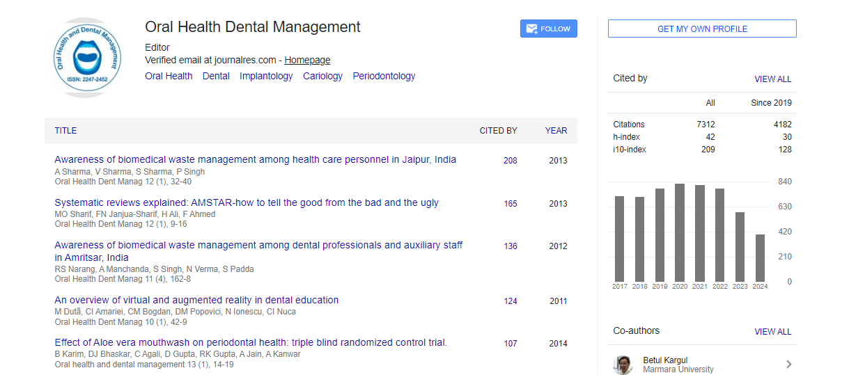

Indexed In
- The Global Impact Factor (GIF)
- CiteFactor
- Electronic Journals Library
- RefSeek
- Hamdard University
- EBSCO A-Z
- Virtual Library of Biology (vifabio)
- International committee of medical journals editors (ICMJE)
- Google Scholar
Useful Links
Share This Page
Journal Flyer
Open Access Journals
- Agri and Aquaculture
- Biochemistry
- Bioinformatics & Systems Biology
- Business & Management
- Chemistry
- Clinical Sciences
- Engineering
- Food & Nutrition
- General Science
- Genetics & Molecular Biology
- Immunology & Microbiology
- Medical Sciences
- Neuroscience & Psychology
- Nursing & Health Care
- Pharmaceutical Sciences
Review Article - (2021) Volume 20, Issue 11
A Review on Lingual Orthodontics
Khushali Rathod*, Shailesh Shenava, Rohit Kulshretha, Prakash Mudaliar, Robin Mathew and Sandeep Singh
Abstract
Change is the only thing which is constant. With the increase in the number of adult patients seeking orthodontic treatment there was a slight downfall in relation with acceptance of orthodontic treatment due to poor aesthetics. The limitations with the previous method were the prime reason of coming up will something more aesthetic and patient friendly. The fact that treatment could be carried out making it look less conspicuous drove the attention of patients as well as the practioners. Thus, there was more research on the bracket type, the basic difference between labial and lingual orthodontics in terms of biomechanics, anchorage control treatment planning and execution. Precise bracket positioning in extremely important to achieve good quality results, this further up surged interest in the laboratory procedure which would help to obtain desirable results. This article thus provides a fair overview of how lingual orthodontics differs from labial orthodontics in many aspects and the need to study it in greater detail.
Keywords
Lingual orthodontics, Laboratory procedures, Biomechanics.
Introduction
Aesthetics is important because it elevates your mind. To be able to think in terms of aesthetics enables demands you to think on a broader perspective. Many patients declined orthodontic treatment in the past because of their preconceived notion of “tinsel teeth” and “metal mouth” The orthodontic specialty has always given esthetics prime importance; Orthodontics dominated the era of esthetic dentistry many years— orthodontists were aligning teeth and creating beautiful smiles long before the rest of the dental disciplines. However, despite our patients’ esthetic concerns regarding the appliances we used, the best we could offer them were smaller steel brackets and ceramic brackets [1].
“Necessity Is the Mother of Invention” Says the proverb. So, applies with the invention of the lingual orthodontic technique by Dr. Craven Kurz. The desire, need for orthodontic correction amongst the adolescence, which comprise the mature group undergoing correction obliged for treatment which was invisible. Lingual orthodontic thus forms an alternative to conventional treatment, designed to satiate those patients who wish to have their teeth aligned but do not want labial brackets [2].
The lingual appliance is no panacea; but, on careful selection of patients, lingual braces can contribute to the contemporary orthodontist’s armamentarium and provide much-needed care for that segment of the population who need these services but, up till now, refrained due to esthetic concerns.
Despite its popularity, we as orthodontists are aware that aligners do have their limitations and are by no means the answer for all malocclusions [3]. Lingual orthodontics thus seems to be a good alternate for catering the requirements of the patients without damaging the biomechanical efficiency in addition considering esthetics goals [4].
Historical Perspective
The evolution of Lingual orthodontics was not a smooth sailing one. There was a period of initial euphoria as the technique made its clinical debut; this was followed by a period of frustration, disappointment, and rejection followed by acceptance [5]. The period of 1970’s was exhilarating for the orthodontist. Curiously, the lingual appliance was not the outturn of an esthetic need, but it was started in Japan by Kinja Fujita [6-10] to treat the patients who practiced martial arts, so as to protect their soft tissues (lips and cheeks) from the possible injury due to impact from brackets. The brackets proposed by Fujita comprised of three slots—occlusal, horizontal, and vertical (Figure 1).

Figure 1: Patent for the Fujita lingual brackets (US patent No. 4,209,906).
Craven Kurz along with Jim Mulick started his investigations in 1975, where he used plastic brackets bonded to the lingual surfaces of tooth. Parallelly an employee with crowded teeth member of the Bunny Playboy Club arrived at Craven Kurz office enquiring him for nonvisible orthodontic treatment. This further prompted Dr Kurz enthusiasm to explore this subject. Patent for the Craven Kurz lingual bracket (Figures 2 and 3). The ease to reshape plastic brackets to facilitate better fit on the lingual surfaces encouraged their use however, sooner many difficulties were witnessed especially those concerning bonding failures and patient amenity.

Figure 2: Patent for the Craven Kurz lingual bracket (US patent No 4,337,037).

Figure 3: Evolution of Craven Kurz lingual bracket.
The first generation of the Kurz lingual bracket was later developed by two engineers Craig Andreiko and Frank Miller. The Kurz lingual bracket developed and evolved to the 7th Generation Ormco Lingual Bracket in 1990. The features of first generation were a bite plane and rounded margins; hooks were absent and the bracket was large. The presence of the bite plane presented with few benefits:
• Opening the bite anteriorly with possible repositioning of the mandible
• Extrusion of molars,
• Intrusion of incisors,
• Facilitating any expansion and mesiodistal movement of molars uninhibited by occlusal forces.
Subsequently addition of hooks was seen on the canine bracket in the second generation (1980), in the third generation (1981); hooks were added to all brackets and to molar tubes. The fourth generation (1982-1984) brackets had a lower profile to facilitate arch wire insertion. The introduced fifth generation brackets (1985-1986) had pronounced bite plane, with increased torque value, and the molar brackets had an accessory tube for a transpalatal arch. The generation six brackets had elongated hooks (1987-1990), the optional placement of transpalatal arch, and the hinge-cap tube for the second molar (self-ligated bracket). With the seventh generation (1990), the square bite plane became rhomboid shaped, thus increasing the distance between two brackets, with mesiodistally widened premolar bracket for better rotational control.
Ormco founded a Task Force to test and continue their research in this field. The following were the members of this group, Craven Kurz, Jack Gorman, Bob Smith, “Wick” Alexander and “Moody” Alexander, James Hilgers and Bob Scholz and administrators Floyd Pickrel, Ernie Strauch, and Michael Swart. The Task Force was initially appointed with the responsibilities of evaluating the revised appliance design over a two-year period. This was initiated for the following reasons:
1. To help refine bracket design (dimensions, torques, angulations, thickness, etc.),
2. To develop mechanotherapy techniques,
3. To create archwire designs,
4. To discuss treatment sequences, and
5. To determine case selection criteria.
In the United States, pioneers in this field were Kelly [11], who used Unitek labial bracket on the lingual surfaces, and Paige [12,13], who used Begg light wire brackets on the lingual surfaces. Creekmore [14] developed a complete technique with vertical slot lingual brackets, together with a laboratory system (The Slot Machine). Thereafter different associations were formed in varied parts of the world which contributed to the existing literature
Instruments used in Lingual Orthodontics
Access to the lingual surface of tooth is a difficult task and cannot be carried out with the set of conventional instruments. Thus, special instruments were designed by the ETM Corporation. These instruments possessed longer handles with beaks angulated either at 45 Ì?/90Ë? which enabled better access.
1. Lingual Ligature Cutter-Angulated 45°-Used for cutting ligature wires and tucking of the ligature wire ends (Figure 4).

Figure 4: Lingual ligature cutter- angulated 45°.
2. Kurz Ligature wire cutter -It is angulated at 90°. It works in similar way as 45° cutter (Figure 5).

Figure 5: (A,B) Kurz ligature wire cutter.
3. Kurz Utility Plier-It is similar to traditional Weingart utility plier with 45° angle (Figure 6).

Figure 6: (A,B) Kurz utility plier.
4. Kurz Archwire Cutter -It functions as distal end cutting plier. The long body provides access to the depth of mouth (Figure 7).

Figure 7: (A,B) Kurz archwire cutter.
5. Kurz Mosquito Forceps (curved) 45 Ì?-Facilitates the placement of elastics and elastic chains (Figure 8).

Figure 8: (A,B) Kurz mosquito forceps (curved) 45Ë?.
6. Light ligature plier, Mathieu style plier (Figure 9).

Figure 9: Light ligature plier, Mathieu style plier.
7. Direct bond removing Plier-The design of the plier was such that it fitted under hooks of Kurz- Ormco brackets. The advantage was it didn’t exert any torque pain on the tooth when debonding (Figure 10).

Figure 10: (A,B) Direct bond removing plier.
8. Kurz tongue retractor and Saliva ejector-It has a dual function of maintaining a dry working field and keeping tongue away from lingual surface of teeth (Figure 11).

Figure 11: (A,B) Kurz tongue retractor and saliva ejector.
9. Kurz First order bending fork-With this plier the clinician can place the first order bends directly in the mouth on the wire thus eliminating the need to replace all the modules or metal ligatures (Figure 12).

Figure 12: Kurz first order bending fork.
10. Kurz Second Order Bending Fork-Both the second order intraoral bends and right-angled bends at the distal sheath can be placed (Figure 13).

Figure 13: (A,B) Kurz second order bending fork.
11.Module Remover (Figure 14).

Figure 14: (A,B) Module remover.
Laboratory Procedures in Lingual Orthodontics
Placement of bracket at correct position is of prime importance in lingual orthodontics. This is because of the variable crown morphology which influences the bracket placement. The following reasons enlighten us the need for having special laboratory procedures to obtain accurate bracket positioning.
1. Variation in height: Variation in height alters the effective torque. Knosel et al. [15] evaluated the changes in incisor third- order inclination resulting from vertical variation in lingual bracket placement in a cephalometric study and reported torque change of 0.4-0.7 degree for each degree of change in inclination of lingual surface (Figures 15A and 15B).

Figure 15: (A) Variation in height.

Figure 15: (B) Variation in Height Alters The Effective Torque.
2. Variation in labiolingual thickness: Brackets placed at the same height on teeth of different labiolingual thickness will be at different distances from labial surface and will position the teeth irregularly labio-lingually (Figure 15C).

Figure 15: (C) Variation in Labiolingual Thickness.
3. Variation in lingual slope angulation (Figure 15D).

Figure 15: (D) Brackets Placed at The Same Height
4. Variation in bracket placement: Changing the angulation of bracket placement instrument can vary crown and root torque (Figure 15E).

Figure 15: (E) Altering the angle of the bracket-positioning instrument.
Laboratory Procedures in Lingual Orthodontics
In lingual orthodontics for precision purpose it’s essential to customize bracket base for tip, torque, and thickness. This led to the introduction of various laboratory techniques in lingual orthodontics. Thereafter different authors came up with specialized devices, incorporated digital technology (Computer-aided designing/computer-aided manufacturing) and made use of robots for wire-bending robots broadening the horizon of treatment.
Main laboratory procedures used for lingual orthodontics
1. Custom Lingual Appliance Setup Service (CLASS System)
2. Torque Angulation Reference Guide (TARG) System
3. Bonding with Equal Specific Thickness (BEST) System
4. Slot Machine
5. Lingual Bracket Jig (LBJ)
6. Transfer optimized positioning
7. Korean Indirect Bonding Set-up (KIS) System
8. Hiro system convertible resin core system
9. Hybrid core system
10. Simplified technique
11.The ray set
12. Orapix system
13. Modified resin core indirect bonding technique
14. Torque angulation device-bracket positioning device
15. Hybrid hiro
16. Incognito fully customized appliance
1. Custom Lingual Appliance Setup Service (CLASS System): Impression obtained with rubber base impression material are duplicated and sectioned for the diagnostic set up. A detailed prescription sheet is made with the necessary instructions. A final wax restoration of the gingiva is then completed and the lingual surfaces are cleaned using a wax solvent. A model release is applied followed by drying in an oven at approximately 100 degrees F for 1 hour. Brackets are placed on the ideal set-up model with the occlusal plane parallel to a fixed horizontal reference. Brackets are bonded on the set-up model using a two-part heavy body. Brackets are placed on the anterior and posterior teeth using an ideal template made of .018 or .022 stainless steel (Figure 16).

Figure 16: Steps in fabrication for CLASS.
A photographic copy is made using a camera or a copying machine to serve as a guide for fabrication of an ideal arch template. Brackets are transferred from the ideal set-up back to the malocclusion model. Malocclusion models with the transferred brackets are copy machined again for a second occlusal record to fabricate the first series of lingual arch wires. Lingual ball hooks are blocked out using an injectable silicone. Transfer trays are fabricated on the malocclusion cast and sectioned in two or three pieces per arch. The trays are cleaned to remove any residue material, the composite pad is etched and the tray is labeled and placed safely until the bonding appointment. Lingual arch wires can be fabricated using templates made from the ideal set-up and malocclusion photographs.
2. Torque Angulation Reference Guide (TARG) System: The TARG machine was launched by the Ormco Society in 1984 as an important aid to the laboratory technique [16]. It allows the accurate placement of the brackets at a precise distance from the incisal and occlusal surfaces of the teeth, as well as making it possible to prescribe the torque and angulation for each tooth individually. The TARG system was comprehensively described by Altounian in 1985. As the TARG machine does not take into consideration the different thickness of the teeth, many second order arch wire bends must be made routinely during treatment.
3. Bonding with Equal Speci ic Thickness (BEST) system: In 1986, Fillion [17] developed a new system. He added a precise measuring device to the original TARG machine called the Electronic TARG and a computer-generated arch wire tracing called DALI (Dessin de’ Arch Lingual Informatise). The new laboratory technique was called the BEST system. It reduces the need for second and third order bends and eliminates the necessity of a set-up model. The biggest advantage being clinical coordination of upper and lower arch wire is not essential as the computer does it.
4. Slot machine: The slot machine was designed by Thomas Creekmore for the placement of both conventional and lingual brackets directly onto the malocclusion model. The machine orients the bracket slot with the Andrews labial arch wire plane (LA plane) keeping in mind the torque and angulation. Difficulty in managing the many pieces of the slot machine might be seen as a disadvantage [18].
5. Lingual Bracket Jig (LBJ): The LBJ developed by Geron is the only system that allows direct as well as indirect positioning of brackets. It consists of a set of six jigs for the anterior maxillary teeth, one universal jig for the posterior teeth, and a special ruler. The jigs transfer the Andrews labial bracket prescription to the lingual surface. Its main disadvantage is the limited number of prescription jigs available [19].
6. Transfer optimized positioning: In addition to the horizontal and vertical measuring systems this technique utilizes the TARG Professional, which has a bracket holder for twin brackets and tubes to find the optimal height for the brackets. The thickness difference in this technique is compensated by arch wire bending. A computer-controlled bending robot (Orthomate lingual module) [20] (OrthoTel, Berlin, Germany/Dallas, TX) automatically generates the arch wires sequence for each case. Bracket and base are custom cast in gold as one unit for each individual tooth (Incognito iBRACES system). Customization improves the accuracy of treatment by allowing the prescription of each tooth to fully express [21,22].
7. Hiro system: In this system no special equipment are required. The Hiro system was created by Toshiaki Hiro and improved by Kyoto Takemoto and Giuseppe Scuzzo. The setup model is sectioned, aligned and brackets are positioned on the set-up model with the help of a full-sized rigid rectangular arch wire (0.018 × 0.025 inches). Individual transfer trays are fabricated for each bracket and transferred directly from the set- up model to the mouth. This method has its own limitations which include longer chair side bonding time, if at any stage there arises a need to rebond the brackets, new transfer trays must be fabricated with reference to the original set-up model [23].
8. Korean Indirect Bonding Set-up (KIS) System: The KIS system was developed by members of the Korean Society of Lingual Orthodontics (KSLO). All the brackets are placed at once with the assistance of a bracket-positioning machine. The precise bracket positioning eliminates the need for repositioning, it allows for bracket height differences between anterior and posterior teeth. Root torque can be incorporated by minimizing the resin thickness between the bracket base and the lingual surface of the tooth. It is simpler and faster. The disadvantage being the need to create a set-up model [24].
9. Convertible resin core system: The Convertible Resin Core system uses hard resin to prepare the individual transfer trays and an elastomeric ligature to hold the tray and bracket together. This allows accurate repositioning of the bracket within the resin core and the trays can be reused in cases of bracket failure
10. Hybrid core system: This is more of a bracket-transfer system. The particular system was developed by Matsuno. This amalgamates the favorable properties of silicone and composite resin in the fabrication of its indirect transfer tray. This combination permits easy retrieval of silicone form bracket and good stabilization of tray intraorally [25].
11.Simplified technique: The Simplified Technique is associated with the development of the new STb brackets. The anterior brackets should be at 1.5 to 2.0 mm from the incisal edge, canines at 2.5 to 3.0 mm on the malocclusion model by using a bracket placement plier or simple tweezers. An individual transfer tray is created for each tooth using a glue gun. There is a need to add compensating bends to the arch wire as this system does not make for variation in tooth thickness.
12. The RAY SET: The RAY SET is further evolution in indirect bonding devices. This was put forth by Takemoto and Scuzzo. It considers each tooth as an individual unit, virtually isolates it from the arch and then places it at the centre of a 3-D control system in which respective first, second and third order values are determined. The device itself is a 3-D Goniometer control system consists of the RTT (Rotation Tip and Torque) cast holder base and PRC (Plane Rotational Control) template essential for preliminary analysis of the first order positions of teeth.
13. Orapix system: A scanner will scan a patient’s model and create a (3D) data file. The orthodontist will receive the 3D data file of the patient and a 3-Txer software package via the Internet. With the 3-Txer software the orthodontist will visualize a 3D model and will be able to create his own virtual set-up on his computer for that particular patient. The orthodontist will decide on the required angulation, torque, curve of the arch, and any other adjustments of the occlusion. All this will be easily visualized on the computer screen. The information is sent back to the laboratory via the Internet and a computer software program will design the transfer trays. A Rapid Prototype (RP) machine will build the transfer trays in resin. A technician will then position the brackets in the transfer trays and add the resin pad on the back of the brackets to finish the process. The main concept behind this technique is to make use of the precise bracket positioning produced by the computer software as opposed to using a technique that is dependent on human hands and eyes, as is the case for most other techniques [26].
14. Simplified manual setup and customization by resin core indirect bonding technique: It’s a modified resin core indirect bonding technique. The Hiro system (originally named as resin core indirect bonding system) does not require the use of any specialized devices and relies on the fabrication of a full dimension lingual arch wire. The manual setup is made by separating teeth from the malocclusion model. This is a simplified laboratory procedure for making the manual setup based on a modification of Hiro technique [27].
Anchorage in Lingual Orthodontics
Anchorage control possesses a challenge in both labial and lingual orthodontics. It is easier to control vertical anchorage in lingual orthodontics because of its inherent tendency to minimize molar extrusion. Initially the bite plane effect in the anterior region tends to extrude the molar [28,29]. However, this effect can be offset by giving acrylic supports over the posterior teeth. Literature suggests that the lingual technique provides superior anchorage control because of the smaller arch perimeter thereby increasing rigidity [30].
There was a study conducted by Takemoto to compare anchorage loss in labial versus lingual extraction cases treated with loop mechanics and he observed higher anchorage value of the posterior dentition in lingual cases [31,32]. The reason being the close proximity of the lingual brackets to the center of resistance of the tooth. In addition, greater amount of cortical anchorage is obtained owing to the direction of forces during space closure which creates a degree of buccal root torque and distopalatal rotation of the molar crown [33].
Mechanics used to control anchorage in upper arch: Lingual treatment offers certain advantages when compared to labial treatment. They are (Figure 17)

Figure 17: Lingual treatment offers certain advantages when compared to labial treatment.
1. Buccal root torque.
2. Distal rotation of molars.
3. An intrusive force is applied.
Lower arch: Anchorage values in lower arch are higher than that in the upper arch, because, the mandible has a thick cortical layer and thinner cancellous layer of base. Sliding mechanics rather than loop mechanics are used for space closure because.
1. Sliding mechanics minimize bowing effect.
2. If avoids tongue irritation from loops.
3. A buccal sectional arch in the percussion segment is unusually used due to high anchorage value in the lower arch.
Loop mechanics are used in space when sliding mechanics are not a good choice. These instances are as follows:
1. A class III malocclusion treated non–surgically.
2. When the extraction spaces are asymmetric.
3. Root contact with cortical bone.
4. Fence effect.
5. While using lingual elastics, they create a fencing effect on the tongue musculature so that it does not act on the dentition. This “fence effect” is probably responsible for increased anchorage value seen in lingual appliance (Table 1).
| Maxilla | Mandible | |
|---|---|---|
| Maximum anchorage | Helical or T–loop along with transpalatal arch and a buccal sectional arch. head gear and class II elastics. | Elastic power chain is used with a buccal sectional arch for stabilization. Class III elastics are used both buccal and lingually for reinforced anchorage. |
| Moderate anchorage | L–loop mechanics with transpalatal arch/ power chain. | Power chain from canine to second premolar on both sides is used. |
| Minimum anchorage | Power chain is placed both on the buccal and lingual of the canine and first molar class III elastics. | An elastic power chain placed circularly from the lingual of the first molar, encircling the canine and attaching to the buccal of the first molar class II elastics. |
Table 1: Loop mechanics are used in space when sliding mechanics are not a good choice.
Lingual Biomechanics
Lingual appliance has certain benefits over labial appliance with reference to the point of force application in relation with centre of resistance. The distance between lingual bracket and Cres in the sagittal plane is much shorter in comparison with this distance in labial orthodontics. Thus, in lingual orthodontics we are able to achieve pure intrusion as point of force application is closer to Cres there will be bodily movement (Figure 18A).

Figure 18: (A) In lingual orthodontics we are able to achieve pure intrusion as point of force application is closer to cres there will be bodily movement.
Control of incisor torque or preservation is more difficult in lingual orthodontics. This occurs because the vertical distance between the brackets and Cres is more in lingual orthodontics than labial orthodontics. Therefore, retractive movement in lingual will result in a greater moment of force than in Labial orthodontics for the same applied load (Figure 18B).

Figure 18: (B) Control of incisor torque or preservation is more difficult in lingual orthodontics.
Liang et al. [34] compared the torque control in labial and lingual appliances using 3-D FEM study and conclusively proved the increased need for torque control in lingual appliance. They focused on the importance of increasing lingual root torque, vertical intrusive force and need to decrease horizontal retractive force to achieve the best orthodontic results.
For upper molars, the axis passing through CR is closer to lingual surface. This implies that whenever an intrusive force is applied to the lingual brackets, the crowns of teeth will rotate in lingual direction; the opposite will occur when intrusive force is applied from labial direction. For lower molars, there is no significant difference in position of brackets because axis to centre of resistance is passing through the middle of the molars.
Another difference is determined by an interdental point of contact, which is more labial in the posterior section. The interproximal space and embrasure gained on the lingual side because lingual force along horizontal plane, generating more crown rotation than would be generated by labial force.
Comparison of Labial and Lingual Biomechanics
Since the biomechanics vary when the appliance is bonded on the lingual surface it is essential to evaluate this difference in sagittal, vertical and horizontal planes of space [35].
1. Sagittal plane: When equal amount of force applied is applied in both systems so that intrusion force F equals the retraction force FR we observe different results. Using the labial system, the net force vector is pointed directly towards Cres. However, in lingual orthodontics the net force vector produces lingual tipping force and vertical bowing effect. Thus we should minimize the retractive force during en masse retraction, increase intrusion and torque force in the anterior to offset the above effects (Figure 18C).

Figure 18: (C) Vertical
2. Vertical plane: When using lingual mechanics, the maxillary incisors are best intruded along their long axis into the broadest area of the alveolar process because the point of application of the force is closer to the long axis of centre of resistance of the incisors.
If the root tips are forward and the crowns are lingually inclined (as in Class II div 2 malocclusion), the intrusion should, however be controlled because the point of application of force is distal to the axis passing through CR of incisors and hence increases the lingual inclination of the crowns. Hence it is advisable first to correct inclinations and later perform intrusion.
3. Horizontal plane: The teeth are positioned along geometrically elliptical arches in the occlusal plane (parallel to the horizontal plane). In the occlusal plane the inter-bracket distance in lingual orthodontics is shorter than the labial one (Figures 18D and 18E).

Figure 18: (D,E) The teeth are positioned along geometrically elliptical arches in the occlusal plane.
Conclusion
This causes increase in arch wire stiffness increases and rotational moment is less than on labial side. Also, in lingual mechanics the point of application of force is closer to the tooth axis. These anatomical factors require important biomechanical considerations.
It is more difficult to have an efficient coupling of forces on lingual side during rotational movement. The rotational moment is less on the lingual side than on labial. In cases of crowding it is more difficult to engage the arch wire in the lingual brackets than in labial, so we need to use more resilient wire.
Just by going through the history and judging the present status, one can say that lingual orthodontics has bright future in the field of orthodontics. With knowledge of this technique, an orthodontist can satisfy esthetic needs of a demanding patient without compromising quality of results.
REFERENCES
- Rafi Romano. Lingual Orthodontics, Becker and Co.1998.
- Echarri P. Lingual orthodontics complete technique, step by step. Nexus Edition. 2004;125(5): 649-650.
- Eikiam Mizrahi. Lingual orthodontics. Semin Orthod. 2006;12(3):151-152.
- Vasumurthy S, Saritha T. Lingual orthodontics. Indian J Dent Adv. 2009;1(1):31-38.
- Echarri P. Revisiting the history of lingual orthodontics: A basis for the future. In Seminars in Orthodontics. 2006;12(3):153-159.
- Fujita K. New orthodontic treatment with lingual bracket mushroom arch wire appliance. Am J Orthod. 1979;76(6):657-675.
- Fujita K. Multilingual-bracket and mushroom arch wire technique: A clinical report. Am J Orthod. 1982;82(2):120-140.
- Fujita K. Development of the lingual brackets technique. A hygienic and aesthetic approach to orthodontic treatment. Ortod Clín.2001;4(3):176-180.
- Fujita K. The Mushroom Archwire and the Lingual Bracket Appliances Philosophy and Technique (manual). Tokyo, Japan, Association of Orthodontists Using the Fujita Method. 1994.
- Alexander CM, Alexander RG, Gorman JC, Hilgers JJ, Kurz C, Scholz RP, et al. Lingual orthodontics. A status report. J Clin Orthod. 1982;16(4):255-262.
- Kelly VM. JCO/interviews Dr. Vincent M. Kelly on lingual orthodontics. J Clin Orthod. 1982;16(7):461-476.
- Raige SF. A lingual light-wire technique. J Clin Orthod. 1982;16:534-44.
- Paige SF. Une technique linguale avec arcs légers. Revue d'Orthopédie Dento-Faciale. 1983;17(3):391-408.
- Creekmore T. Lingual orthodontics: Its renaissance. Am J Orthod Dentofac Orthop. 1989;96(2):120-137.
- Knösel M, Jung K, Gripp-Rudolph L, Attin T, Attin R, Sadat-Khonsari R, et al. Changes in incisor third-order inclination resulting from vertical variation in lingual bracket placement. Angle Orthod. 2009;79(4):747-754.
- Echarri P. Técnica de posicionamiento de brackets linguales Class System. Rev Iberoam Ortod. 1997;16(1):1-7.
- Fillion D. Orthodontie linguale: Systèmes de positionnement des attaches au laboratoire. Orthod Fr. 1989;60:695-704.
- Echarri P. Procedimiento para el posicionamiento de brackets em Ortodoncia lingual. Ortod Clin. 1998;1:69-77.
- Geron S. The lingual bracket jig. J Clin Orthod. 1999;33(8):457-463.
- Wiechmann D. Lingual orthodontics (part 1): Laboratory procedure. J Orofac Orthop. 1999; 60(5):371-379.
- Wiechmann D. Lingual orthodontics (part 2): Archwire fabrication. J Orofac Orthop. 1999;60(6):416-426.
- Geron S, Romano R. Bracket positioning in lingual orthodontics: Critical review of different techniques. Korean J Clin Orthod. 2003;2:39-44.
- Scuzzo G, Takemoto K. Invisible orthodontics: current concepts and solutions in lingual orthodontics.
- Kim TW. Indirect bonding system in lingual orthodontics. Korean J Orthod. 2002;32:38-45.
- Matsuno I, Okuda S, Nodera Y. The hybrid core system for indirect bonding. J Clin Orthod. JCO. 2003 Mar; 37(3):160-161.
- Fillion D. Lingual straightwire treatment with the Orapix system. J Clin Orthod. 2011;45(9):488-497.
- Das SK. Simplified manual setup and customization by resin core indirect bonding technique: Lingual orthodontics on your own. J Indian Orthod Soc. 2016;50(4_suppl1):23-32.
- Hiro T, Takemoto K. Resin care indirect bonding system-Improvement of ligual orthodontic treatment. J Japan Orthod Soc. 1998;57:83-91.
- Buckley J. Lingual orthodontics: An illustrated review with the incognito fully customised appliance. J Ir Dent Assoc. 2012;58(3):149-155.
- Kurz C, Bennett R. Extraction cases and the lingual appliance. J Am Ling Orthod Assoc. 1988;3:10-13.
- Takemoto KY. Anchorage control in lingual orthodontics. In Lingual Orthodontics 1998.75-82.
- Takemoto K. Lingual orthodontic extraction therapy. Clin Impressions. 1995;4:18-21.
- Geron S. Anchorage considerations in lingual orthodontics. Semin Orthod. 2006;12(3):167-177.
- Liang W, Rong Q, Lin J, Xu B. Torque control of the maxillary incisors in lingual and labial orthodontics: A 3-dimensional finite element analysis. Am J Orthod. Dentofacial Orthop. 2009;135(3):316-322.
- Goren S, Zoizner R, Geron S, Romano R. Lingual orthodontics (LO) versus buccal orthodontics (BO): Biomechnical and clinical aspects. J Lingual Orthod. 2003;3(1).